
Sitting sensor

a technology for sitting sensors and sensors, applied in the direction of contact mechanisms, chairs, pedestrian/occupant safety arrangements, etc., can solve the problem of not being able to detect sitting, and achieve the effect of simplifying the wiring design

Active Publication Date: 2021-06-10
THE FUJIKURA CABLE WORKS LTD
View PDF1 Cites 2 Cited by
  • Summary
  • Abstract
  • Description
  • Claims
  • Application Information

AI Technical Summary

Benefits of technology

The invention relates to a sitting sensor that is designed to prevent the pressure-sensitive switches from being separated from each other, even when a stress is applied in a certain direction. This helps to maintain the relative displacement of the pressure-sensitive switches. Additionally, the sensor allows for a more simplified wiring design, as the same wiring can be used for multiple pressure-sensitive switches without having to rise and extend in the left-right direction of the seat. This reduces the complexity of the wiring design and makes it more efficient.

Problems solved by technology

In this case, sitting cannot be detected.

Method used


Image

  • Sitting sensor
  • Sitting sensor
  • Sitting sensor

Examples


first embodiment

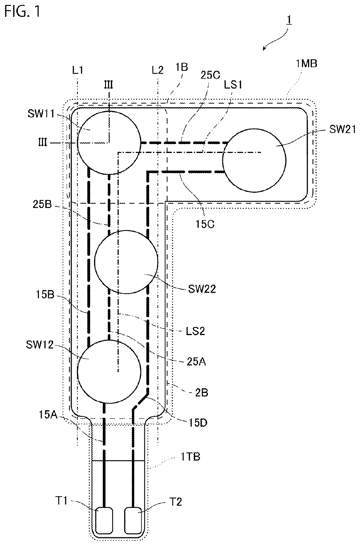
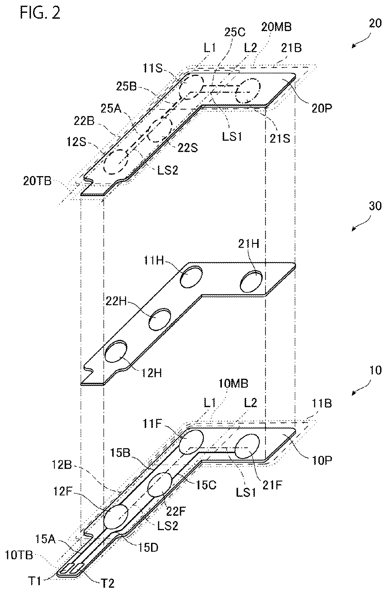
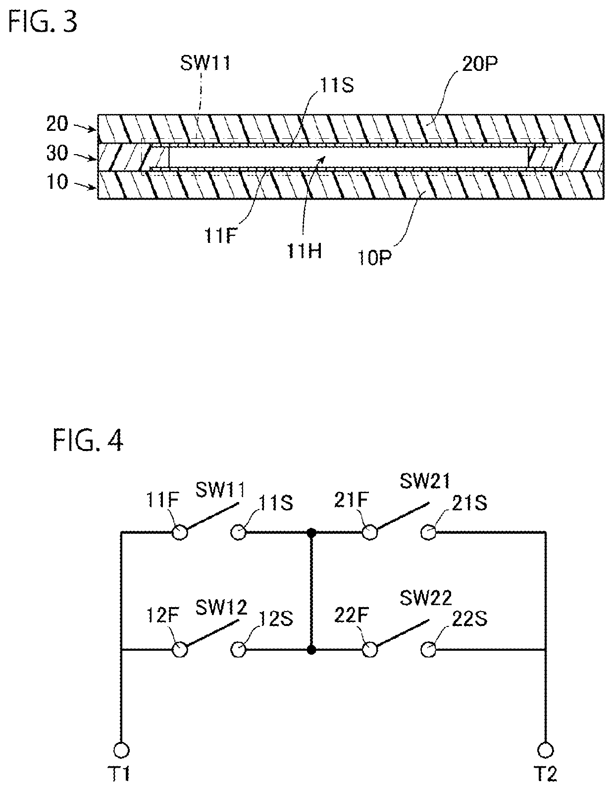
[0046]FIG. 1 is a plan view of the sitting sensor according to the present embodiment. Further, FIG. 2 is an exploded view of a sitting sensor 1 in FIG. 1. As shown in FIG. 2, the sitting sensor 1 includes a first electrode sheet 10, a second electrode sheet 20, and a spacer 30.

[0047]The first electrode sheet 10 as one electrode sheet includes a first insulating sheet 10P as one insulating sheet, first electrodes 11F and 12F, second electrodes 21F and 22F, terminals T1 and T2, and wirings 15A to 15D as main constituent elements.

[0048]The first insulating sheet 10P includes an insulating and flexible sheet. Examples of a material configuring the first insulating sheet 10P include resins such as polyethylene terephthalate (PET), polyethylene naphthalate (PEN), and polyimide (PI). The first insulating sheet 10P includes a substantially L-shaped main block 10 MB and a substantially rectangular tail block 10 TB having a width narrower than that of the main block 10 MB.

[0049]The main bloc...

second embodiment

[0086]Next, a second embodiment will be described. In the description of the present embodiment, constituent elements that are the same as or equivalent to those in the first embodiment will be assigned the same reference numerals and redundant description will not be repeated unless otherwise specified.

[0087]FIG. 7 is a plan view of the sitting sensor according to the present embodiment. FIG. 8 is an exploded view of the sitting sensor in FIG. 7. As shown in FIGS. 7 and 8, the sitting sensor 1 according to the present embodiment is different from the sitting sensor 1 according to the first embodiment in that the sitting sensor 1 according to the present embodiment further includes a third belt 3B having a first pressure-sensitive switch SW13 and a second pressure-sensitive switch SW23, and the distance between the first pressure-sensitive switch SW11 and the second pressure-sensitive switch SW21 is longer.

[0088]The first electrode sheet 10 according to the present embodiment is mai...


PUM


Abstract

A plurality of pressure-sensitive switches of a sitting sensor (1) has a first pressure-sensitive switch group including a first pressure-sensitive switch (SW11) including a first specific pressure-sensitive switch and a second pressure-sensitive switch (SW21), and a second pressure-sensitive switch group including first pressure-sensitive switches (SW11, SW12) including the first specific pressure-sensitive switch, and a second pressure-sensitive switch (SW22), in which in the first pressure-sensitive switch group, the first pressure-sensitive switch (SW11) and the second pressure-sensitive switch (SW21) are disposed adjacent to each other along a left-right direction of a seat (SE), in the second pressure-sensitive switch group, the first pressure-sensitive switches (SW11, SW12) and the second pressure-sensitive switch (SW22) are disposed adjacent to each other along a front-rear direction of the seat (SE), and turning on the first pressure-sensitive switch and the second pressure-sensitive switch causes a current to flow between a pair of terminals (T1, T2).

Description

TECHNICAL FIELD[0001]The present invention relates to a sitting sensor and is suitable for appropriately detecting sitting.BACKGROUND ART[0002]As one safety system in vehicles, an alarm system that warns of an unworn seat belt when an occupant is in a vehicle has been in practical use. This alarm system issues a warning when the seat belt being worn is not sensed while sitting of a person is sensed. As a device that detects such sitting of a person, a sitting sensor that detects sitting by application of a load may be used.[0003]As such a sitting sensor, a sitting detection device of Patent Literature 1 has been proposed. The sitting detection device of Patent Literature 1 has a sheet-shaped upper film and lower film that are overlapped via an insulating spacer, and a plurality of contacts as pressure-sensitive switches linearly arranged with a predetermined space apart to form a rod shape. Further, the plurality of contacts of this sitting detection device has a configuration in wh...

Claims


Application Information

Patent Timeline
Patent Type & Authority Applications(United States)
IPC IPC(8): B60N2/00H01H13/16
CPCB60N2/002H01H13/16B60R21/01516H01H3/141B60N2/0034B60N2/0026B60N2/0033B60N2210/46A47C7/62B60N2/90
Inventor KAWAHIRA, TETSUYAHAYASHI, ERIKO
Owner THE FUJIKURA CABLE WORKS LTD
Learn More