
Method for decorating a mechanical part

a mechanical part and surface technology, applied in the field of mechanical part decoration, can solve the problem of filling material leaking a little on the surface of the mechanical part, and achieve the effect of improving the appearance and appearance of the mechanical par

Pending Publication Date: 2021-06-17
RUBATTEL & WEYERMANN
View PDF6 Cites 0 Cited by
  • Summary
  • Abstract
  • Description
  • Claims
  • Application Information

AI Technical Summary

Benefits of technology

The present invention provides a method for decorating mechanical parts with high-precision decoration elements that are securely anchored to the surface of the part. The method prevents the decoration elements from having smears and ensures that the overall process is cost-effective and efficient as compared to existing methods. Additionally, the method allows for easy adjustment of the shape and thickness of the decoration elements and improves the adherence of the decoration elements on the surface of the part. The method further guarantees a strong resistance of the decoration elements over time.

Problems solved by technology

One drawback of the decoration method using masks placed on the surface of the mechanical part to be decorated can nonetheless be seen in the fact that the risk of the mask not being in close contact with the surface of the mechanical part to be decorated cannot be ruled out, and that when filling the different moulds, there is a risk of the filling material leaking a little on the surface of the mechanical part, which requires some of these mechanical parts to be discarded.
This is in particular problematic when looking to decorate dials for timepieces, since such dials are expensive mechanical parts.

Method used


Image

  • Method for decorating a mechanical part
  • Method for decorating a mechanical part
  • Method for decorating a mechanical part

Examples


Embodiment Construction

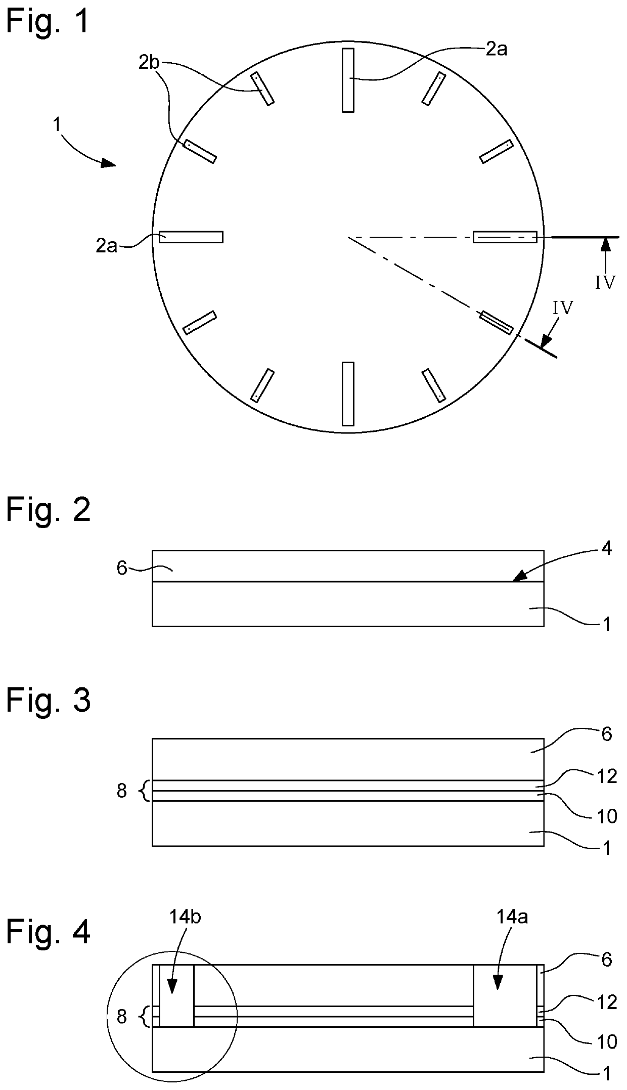
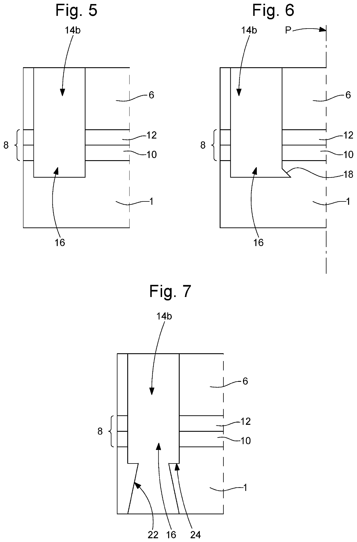
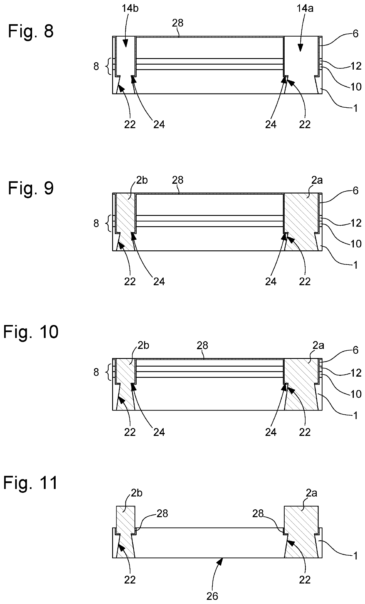
[0062]The present invention proceeds from the general inventive idea consisting of forming decoration elements on a surface of a mechanical part to be decorated, in particular watch dials and more generally external elements of timepieces such as bezels, middles or even bracelet links, in addition to jewellery. In order to achieve this result, the present invention discloses the deposition, directly on the surface to be decorated of the mechanical part, of a mask of the sacrificial type, that is to say a mask that is intended to be removed at the end of the operations for decorating the mechanical part. Once the mask has been deposited in close contact with the surface of the mechanical part to be decorated, then structured so as to create first cavities therein which will be filled with the material in which the decoration elements are to be produced, the surface formed by the top of the mask and the decoration elements undergoes machining and potentially dressing, after which the ...


PUM

PropertyMeasurementUnit
thicknessaaaaaaaaaa
thicknessaaaaaaaaaa
depthaaaaaaaaaa

Abstract

A method for decorating a surface of a mechanical part including: taking the mechanical part to be decorated, on which a decoration element is sought to be produced; depositing on the surface a masking layer having a thickness that is at least equal to the thickness of the decoration element to be produced; making, in the masking layer, at least one cavity that coincides with the location on the surface to be decorated, the cavity having a contour that corresponds to the contour of the decoration element and defining a volume; depositing a bonding layer made of an electrically-conductive material on top of the masking layer and on the surface, in the locations of the cavity, to facilitate the bonding of the decoration element; filling the volume delimited by the masking layer and the surface with a filling material in which the decoration element; and removing the masking layer.

Description

CROSS REFERENCE TO RELATED APPLICATION[0001]This application claims priority to European Patent Application No. 19216709.6 filed Dec. 16, 2019, the entire contents of which are incorporated herein by reference.TECHNICAL FIELD OF THE INVENTION[0002]The present invention relates to a method for decorating a mechanical part. More specifically, the invention relates to a method for decorating at least one surface to be decorated of a mechanical part used in the horological or jewellery field.BACKGROUND OF THE INVENTION[0003]Numerous methods for producing raised decorations on a surface of a mechanical part such as a watch dial or a bezel are known in the prior art. A certain number of these known methods consist of manufacturing the decoration elements separately from the mechanical part to be decorated, then of fastening these decoration elements to the mechanical part for which they are intended.[0004]Another method for decorating a mechanical part such as a dial is known from the Eur...

Claims


Application Information

Patent Timeline
Patent Type & Authority Applications(United States)
IPC IPC(8): A44C27/00C23C14/34C25D1/10C23C14/58G04B45/00
CPCA44C27/006C23C14/34G04B45/0076C23C14/5873C25D1/10G04B19/18G04D3/0048B21J1/006B22D19/00B05D1/32G04B37/22G04B19/10G04B19/12G04B29/027B44C1/227G04D3/0069G04D3/0092C23C14/14
Inventor JEANRENAUD, FRÉDÉRIC
Owner RUBATTEL & WEYERMANN
Learn More