
Suction valve for high-pressure fuel pump

a high-pressure fuel pump and suction valve technology, which is applied in the direction of liquid fuel engines, piston pumps, positive displacement liquid engines, etc., can solve the problems of reduced valve operation speed, inability to control inability to reduce the pressure of the fuel rail, so as to prevent the deformation of the valve sleeve, accurately control the discharge flow, and reduce the effect of discharge flow distribution

Active Publication Date: 2021-06-17
HYUNDAI KEFICO CORP
View PDF2 Cites 0 Cited by
  • Summary
  • Abstract
  • Description
  • Claims
  • Application Information

AI Technical Summary

Benefits of technology

The present patent provides a suction valve for a high-pressure fuel pump that prevents deformation and reduces the discharge flow distribution between products by removing the double press-fitting structure of the valve sleeve. It also prevents self-closing due to backflow of inner fuel. The valve sleeve is assembled using a preset valve lift to accurately control the discharged flow of the pump and pressure of the fuel rail.

Problems solved by technology

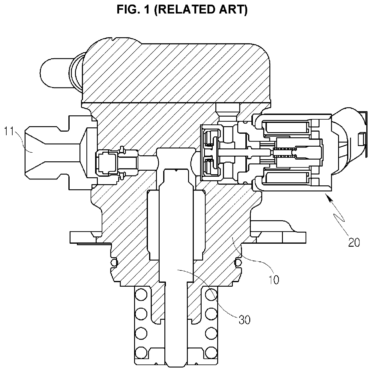
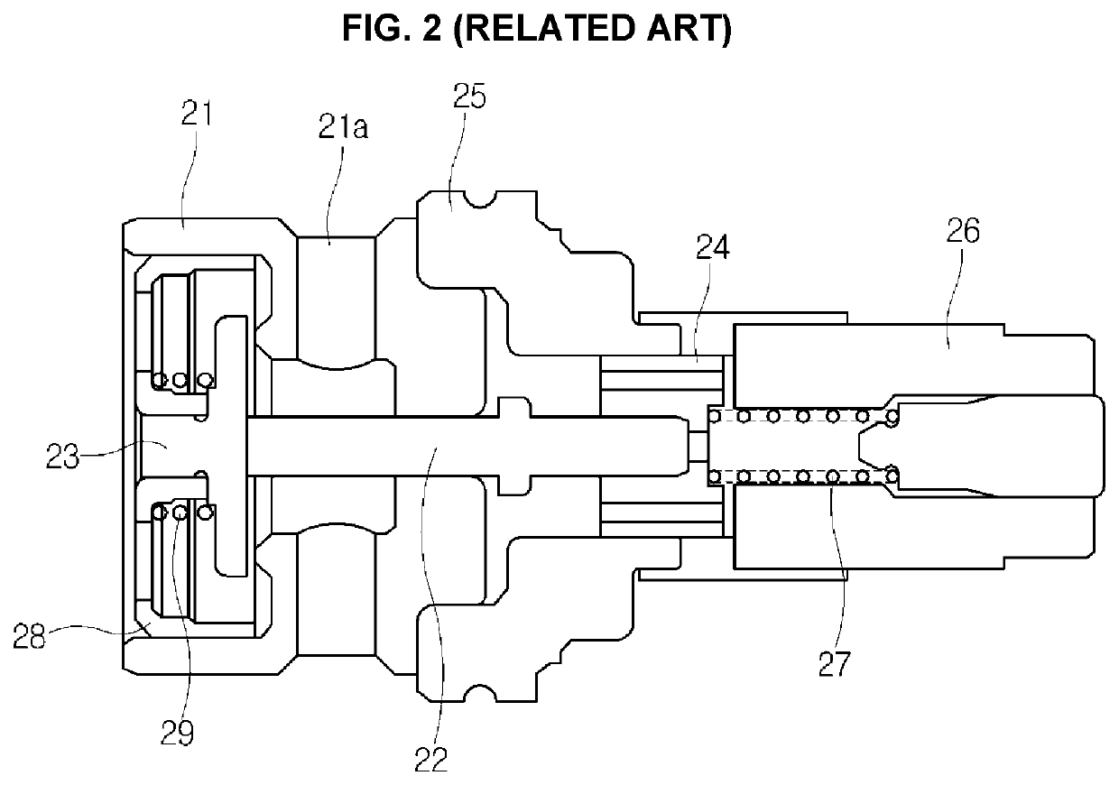
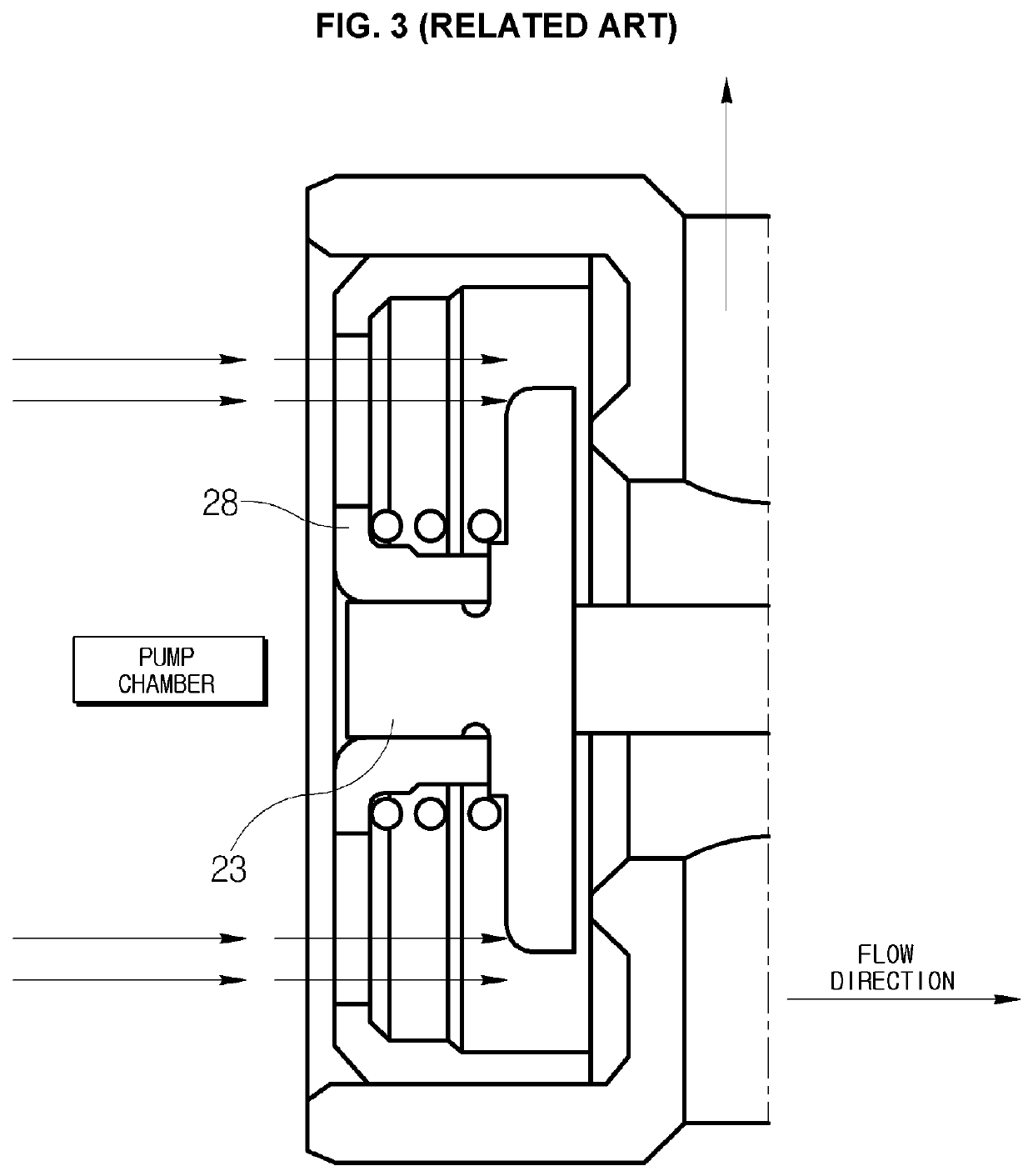
However, there is a problem in that the valve sleeve 28 is deformed every time it is press-fitted, and the valve lift is also changed by a double press-fitting structure which is press-fitted once when the valve sleeve 28 is press-fitted into the valve body 21, and press-fitted once again when the valve body 21 is press-fitted into the housing 10.
As described above, there is a problem in that when the valve lift is changed, the operation speed of the valve is reduced, and when the operation speed is reduced, a discharge flow distribution between products occurs as an amount of fuel charged in the high-pressure chamber is unevenly controlled.
When such a phenomenon occurs, there are problems in that the pressure of the fuel rail is not controlled because the discharged flow is not controlled, and the high-pressure fuel pump discharges the compressed fuel to the fuel rail although it is not controlled.
However, if the return spring with a large force is used, there are problems in that it is not economical and the operation noise is also increased.

Method used


Image

  • Suction valve for high-pressure fuel pump
  • Suction valve for high-pressure fuel pump
  • Suction valve for high-pressure fuel pump

Examples


Embodiment Construction

[0040]It is understood that the term “vehicle” or “vehicular” or other similar term as used herein is inclusive of motor vehicles in general such as passenger automobiles including sports utility vehicles (SUV), buses, trucks, various commercial vehicles, watercraft including a variety of boats and ships, aircraft, and the like, and includes hybrid vehicles, electric vehicles, plug-in hybrid electric vehicles, hydrogen-powered vehicles and other alternative fuel vehicles (e.g. fuels derived from resources other than petroleum). As referred to herein, a hybrid vehicle is a vehicle that has two or more sources of power, for example both gasoline-powered and electric-powered vehicles.

[0041]The terminology used herein is for the purpose of describing particular embodiments only and is not intended to be limiting of the disclosure. As used herein, the singular forms “a,”“an” and “the” are intended to include the plural forms as well, unless the context clearly indicates otherwise. It wil...


PUM


Abstract

A suction valve of a high-pressure fuel pump for a vehicle includes a housing having an inlet through which a fuel is introduced and a pump chamber configured to press the fuel, a valve installation space arranged between the inlet and the pump chamber, and a solenoid part provided with a rod for performing a linear reciprocal motion, and further includes a valve sleeve inserted into the valve installation space and formed with a flow hole, a valve spring seated on the valve sleeve, a valve plate elastically supported by the valve spring, and moving in conjunction with the rod, and a valve sheet formed with an introduction hole opened and closed by the valve plate, in which the valve sleeve is slid and inserted into the valve installation space, and the valve sheet is fitted into and fastened to the valve installation space to support the valve sleeve.

Description

CROSS-REFERENCE(S) TO RELATED APPLICATION(S)[0001]This application claims under 35 U.S.C. § 119 the benefit of Korean Patent Application No. 10-2019-0168518 filed on Dec. 17, 2019, the entire contents of which are incorporated herein by reference.BACKGROUND(a) Technical Field[0002]The present disclosure relates to a suction valve of a high-pressure fuel pump for a vehicle, more particularly, to the suction valve of the high-pressure fuel pump, which can prevent deformation of a valve sleeve, and also can prevent the suction valve from being closed by the fuel which backflows from a pump chamber side.(b) Description of the Related Art[0003]A fuel supply device for a vehicle includes a fuel tank, a fuel rail, and a fuel pump. The fuel rail serves to distribute a high-pressure fuel stored in the fuel tank to each injector. The fuel rail is installed with a plurality of injectors, and each injector is connected to a cylinder head or an intake manifold to inject the fuel into a combustio...

Claims


Application Information

Patent Timeline
IPC IPC(8): F02M59/46F04B53/10F04B7/00F02M59/10
CPCF02M59/46F02M59/10F04B7/0003F04B53/10F02M59/368F02M59/464F04B7/0076F04B1/0456F04B1/053F04B53/1032F04B53/1087F02M59/361
Inventor HAN, KYUNG CHULPARK, HYEONG KYUNKIM, JIN SUNGHONG, CHUN KY
Owner HYUNDAI KEFICO CORP
Learn More