
Method for improving transmission kikuchi diffraction pattern

Active Publication Date: 2021-06-17
BRUKER NANO INC
View PDF0 Cites 2 Cited by
  • Summary
  • Abstract
  • Description
  • Claims
  • Application Information

AI Technical Summary

Benefits of technology

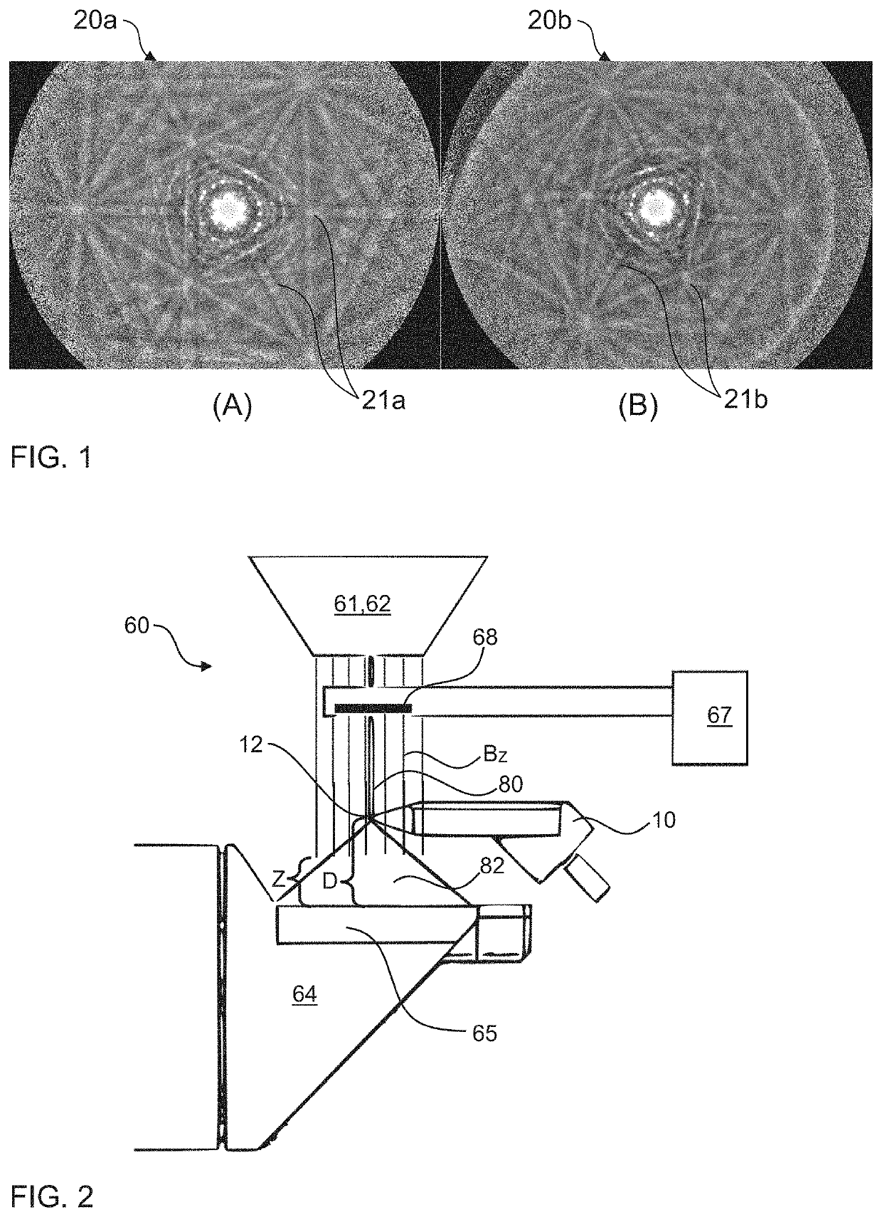
The present invention provides a method for improving a TKD pattern in an electron microscope without needing detailed knowledge of the magnetic field. This is achieved by using general terms that describe geometrical operations of rotation and / or rotation and contraction, based on the geometry of the linear TKD setup in the microscope. The factor φ can be expressed as ϕ=γωDv1+r2D2, where r is the horizontal distance from an improved image point and v is the velocity of an electron. The greater the difference in distance from the symmetry axis of the magnetic field between the improved image points, the greater the distortion. This method allows for better accuracy in TKD pattern measurements.

Problems solved by technology

However, in case of not linearly extending Diffraction bands in the Kikuchi patterns, an erroneous solution for crystal orientation and / or phase or no solution at all might be determined for a data point of the TKD map.
The linear extension of a Kikuchi band may be impaired by at least one electronic optic within the electron microscope, particularly by a magnetic lens.
However, due to such magnetic lens, a residual magnetic field may exist in the SEM chamber that distorts the movements of the electrons.

Method used


Image

  • Method for improving transmission kikuchi diffraction pattern
  • Method for improving transmission kikuchi diffraction pattern

Examples


Embodiment Construction

[0009]The objective of the invention is solved and the disadvantages of the prior art are overcome, at least partially, by the method of claim 1, by the measurement system of claim 12, by the computer program of claim 14 and the computer-readable medium of claim 15. The dependent claims are directed to preferred embodiments of the respective independent claims.

[0010]A first aspect of the present invention relates to a method of improving a Transmission Kikuchi Diffraction, TKD, pattern. Therein, the improvement particularly is that of unwarping a detected Kikuchi pattern in order to enable high precision indexing of the Kikuchi pattern. In a first step of the method of the invention thus a TKD pattern of a sample is detected or determined based on detected signals corresponding to the TKD pattern. Therein, the TKD pattern is detected in an electron microscope that comprises at least one active electron lens that is configured for focussing an electron beam on a point on a sample. In...


PUM


Abstract

The present invention refers to a method for improving a Transmission Kikuchi Diffraction, TKD pattern, wherein the method comprises the steps of: Detecting a TKD pattern (20b) of a sample (12) in an electron microscope (60) comprising at least one active electron lens (61) focussing an electron beam (80) in z-direction on a sample (12) positioned in distance D below the electron lens (61), the detected TKD (20b) pattern comprising a plurality of image points xD, yD and mapping each of the detected image points xD, yD to an image point of an improved TKD pattern (20a) with the coordinates x0, y0 by using and inverting generalized terms of the form xD=γ*A+(1−γ)*B and yD=γ*C+(1−γ)*D whereinγ=ZDwith Z being an extension in the z-direction of a cylindrically symmetric magnetic field BZ of the electron lens (61), and wherein A, B, C, D are trigonometric expressions depending on the coordinates x0, y0, with B and D defining a rotation around a symmetry axis of the magnetic field BZ, and with A and C defining a combined rotation and contraction operation with respect to the symmetry axis of the magnetic field BZ. The invention further relates to a measurement system, computer program and computer-readable medium for carrying out the method of the invention.

Description

[0001]The present invention refers to a method for improving the quality of a Kikuchi pattern obtained using a Transmission Kikuchi Diffraction, TKD, technique. Particularly, an influence of electron optics in an electron microscope used to obtain the TKD pattern shall be reduced. The present invention further relates to a measurement system for performing the method of the present invention as well as to a computer program for performing the method.TECHNOLOGICAL BACKGROUND AND PRIOR ART[0002]Energy dispersive spectroscopy (EDS, also called EDX) is a commonly used X-ray analytic technique for characterizing the elemental composition of a sample based on characteristic X-rays emitted by the sample after being excited by an incident electron beam. EDS measurements are commonly carried out within electron microscopes (EM), such as e.g., scanning electron microscopes (SEM), which comprise suitably configured EDS detectors inside a measurement chamber of the electron microscope. In the E...

Claims


Application Information

Patent Timeline
IPC IPC(8): H01J37/244H01J37/20
CPCH01J37/244G01N23/203H01J37/20G01N23/20058G01N23/2055G01N2223/401G01N2223/102G01N2223/071G01N2223/0566G01N2223/0565G01N2223/605G01N2223/607H01J2237/20207
Inventor SCHWAGER, THOMASGORAN, DANIEL RADU
Owner BRUKER NANO INC
Learn More