
Method for Precision Machining a Workpiece Provided With Gearing

a technology of precision machining and workpiece, which is applied in the direction of gear teeth, gear-teeth manufacturing apparatus, manufacturing tools, etc., can solve the problems of limited relative movements and wear of precision machining tools, and achieve the effect of sufficient long-term durability of workpieces

Pending Publication Date: 2021-06-24
PRAWEMA ANTRIEBSTECHN
View PDF1 Cites 1 Cited by
  • Summary
  • Abstract
  • Description
  • Claims
  • Application Information

AI Technical Summary

Benefits of technology

The invention is a method for machining gearing on workpieces using a gear-cutting tool. The method is designed to maximize the removal of material from the tooth flanks of the gear teeth during the process. The method can be used with different types of gear-cutting tools and can even be implemented by moving only the workpiece in the axial direction while the gear-cutting tool remains stationary. The method can also be used to create specific form elements on the teeth of the workpiece by aligning the rotation axes of the workpiece and the gear-cutting tool. The tool used for machining can be dressed to ensure optimal size accuracy and durability of the workpiece. The method allows for precise machining of gears with internal teeth and can even be used with workpieces that rotate during machining.

Problems solved by technology

The precision machining leads to wear on the precision machining tool.
However, these relative movements are limited such that the gear-cutting tool and the workpiece always remain in engagement.
On the basis of the prior art explained above, the problem that arises is that of creating a method for precision machining workpieces with gearing, with which it is possible to achieve further enhanced removal material performance along with long-term durability.

Method used


Image

  • Method for Precision Machining a Workpiece Provided With Gearing
  • Method for Precision Machining a Workpiece Provided With Gearing

Examples


Embodiment Construction

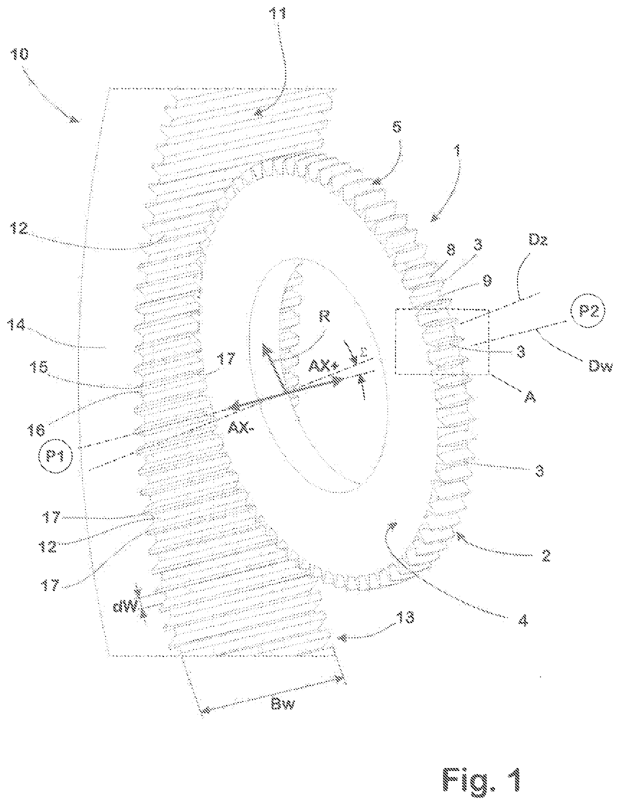
class="d_n">[0036]The gear-cutting tool 1 produced from a material typically used in the prior art is held in a tool holder, which is not shown here for the sake of clarity and which in turn is coupled in a manner known per se to a rotary drive, via which the gear-cutting tool 1 in use is driven to rotate about a tool rotation axis Dz.

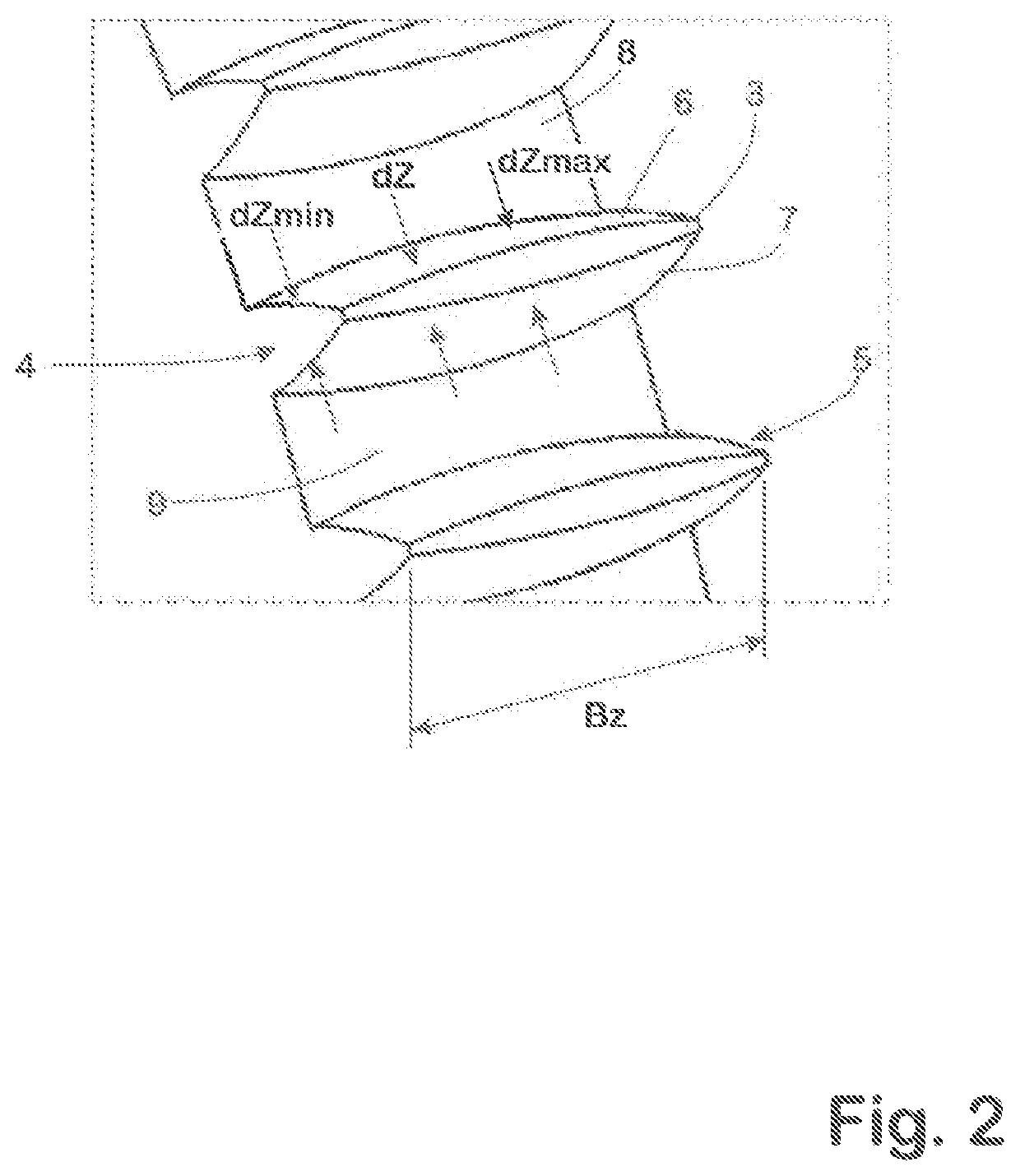
[0037]The gear-cutting tool 1 has an external gearing 2 configured as spur gearing, which is formed in standard fashion by a multiplicity of teeth 3 distributed at uniform angular distances about the tool rotation axis Dz. The teeth 3 are each aligned in an axis-parallel manner to the tool rotation axis Dz, and extend over the width Bz of the gear-cutting tool 1, between the end faces 4, 5 of the gear-cutting tool 1.

[0038]Each tooth 3 has tooth flanks 6, 7, one of which in each case is assigned to the tooth gaps 8, 9 of the gearing 2 of the gear-cutting tool 1, which are bordered on one of their sides by the corresponding tooth 3. The tooth flanks 6, 7...


PUM

PropertyMeasurementUnit
thicknessaaaaaaaaaa
width Bwaaaaaaaaaa
width Bzaaaaaaaaaa

Abstract

For the precision machining of a workpiece (10) provided with gearing (11) and rotating about a rotation axis (Dw), teeth (3) of a gear-cutting tool (1) rotating about a rotation axis (Dz) are brought into engagement with teeth (12) of the workpiece (10), and the gear-cutting tool (1) and the workpiece (10) are moved relative to each other in a direction (AX+, AX−) parallel to the rotation axis (Dw). The thickness (dZ) of the teeth (3) of the gear-cutting tool (1) increases in the axial direction, starting from the respective front ends (4, 5) of the teeth, until a thickness maximum (dZmax) is reached. High material removal performances and long-term durability of the gear-cutting tool (1) are achieved in that, according to the invention, 2≤Bw / Bz≤20 applies (wherein Bw=width Bw of the teeth of the gearing (11) of the workpiece (10), Bz=width of the teeth (3) of the gear-cutting tool (1)), that the gear-cutting tool (1), before each pass of its teeth (3) through the tooth gaps (17) of the workpiece (10) in the respective axial directions (AX+, AX−), is positioned at a position (P1, P2) in which the thickness maximum (dZmax) of the teeth (3) of the gear-cutting tool (1) is situated outside the gearing (11) of the workpiece (10), and that as a consequence of the relative movement of the workpiece (10) and of the gear-cutting tool (1) in the axial direction (AX+, AX−), the teeth (3) of the gear-cutting tool (1) are each moved through the respective tooth gaps (17) of the gearing (11) of the workpiece (10) that are assigned to them, until the thickness maximum (dZmax) of each tooth (3) has exited the assigned tooth gap (17).

Description

CROSS-REFERENCE TO RELATED APPLICATION[0001]This application claims priority to German Patent Application No. 10 2019 134 924.9 filed Dec. 18, 2019, the disclosure of which is hereby incorporated by reference in its entirety.BACKGROUND OF THE INVENTIONField of the Invention[0002]The invention relates to a method for precision machining a workpiece provided with gearing, in which teeth of a gear-shaped gear-cutting tool, which rotates about a rotation axis, are brought into rolling engagement with teeth of the gearing of the workpiece rotating about a rotation axis while the gear-cutting tool and the workpiece are being moved relative to each other in a direction parallel to the rotation axis of the workpiece, wherein the thickness of the teeth of the gear-cutting tool increases to a thickness maximum, in each case starting from the end face of the teeth that faces forward with respect to the corresponding movement in the axial direction.Description of Related Art[0003]The precision ...

Claims


Application Information

Patent Timeline
Patent Type & Authority Applications(United States)
IPC IPC(8): B23F1/06
CPCB23F1/06B23F19/05B23F5/00B23F21/03B23F5/163B23F5/02B23F1/02
Inventor SCHIEKE, JÖRGHOLDERBEIN, WALTERREINHARDT, JÖRG
Owner PRAWEMA ANTRIEBSTECHN
Learn More