
Linear object removal method, linear object removal device, and electronic/electric apparatus component scrap processing method

Active Publication Date: 2021-07-01
JX NIPPON MINING& METALS CORP
View PDF0 Cites 1 Cited by
  • Summary
  • Abstract
  • Description
  • Claims
  • Application Information

AI Technical Summary

Benefits of technology

The present patent provides a method, device, and method for processing electronic / electrical apparatus component waste that can efficiently sort wire-form objects from sorting target objects having various shapes. The method involves improving the shape of filters arranged in a vibrating sieve machine to remove wire-form objects from sorting target objects. This solution is designed to solve the problems of efficiently removing wire-form objects that are often present in electronic / electrical apparatus component waste.

Problems solved by technology

As described in Patent Literature 2, when the incinerated electronic / electrical apparatus component scrap is processed in the blast furnace, the presence of refining inhibitors such as aluminum, antimony, iron and nickel in the electronic / electrical apparatus component scrap may decrease a processing efficiency of the blast furnace for processing the scrap.
However, under the circumstances, it is difficult to selectively separate and recover desired single components from a wide variety of component scrap having various shapes, and various studies have been made.
The wire-form objects are easily entangled with other components and / or equipment when sorting desired single components from a wide variety of component scrap having various shapes, which may cause deterioration of separation accuracy and equipment troubles.

Method used


Image

  • Linear object removal method, linear object removal device, and electronic/electric apparatus component scrap processing method
  • Linear object removal method, linear object removal device, and electronic/electric apparatus component scrap processing method
  • Linear object removal method, linear object removal device, and electronic/electric apparatus component scrap processing method

Examples


Embodiment Construction

[0022]Hereinafter, embodiments of the present invention will be described with reference to the drawings. The embodiments as shown below illustrate devices and methods for embodying the technical idea of the present invention, and the technical idea of the present invention does not limit structures, arrangement, and the like of components to those described below.

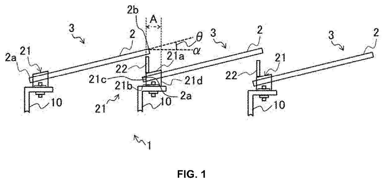
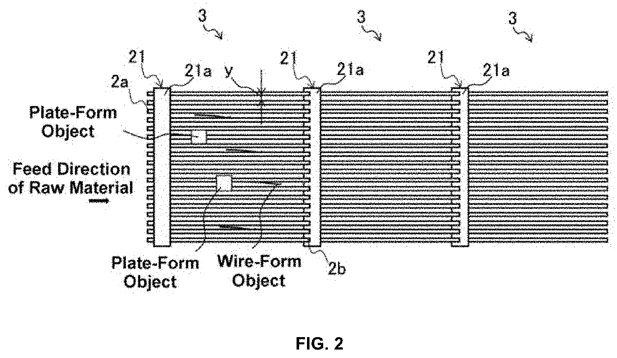
[0023]As shown in FIG. 1, a device for removing wire-form objects according to an embodiment of the present invention includes a plurality of filters 3 which are fixed to fixing portions 10 arranged in a vibrating sieve machine 1 (a vibrating sieve machine body), and which are arranged adjacent to each other in a feeding direction of a raw material. The plurality of filters 3 are vibrated by a vibrator (not shown), so that the raw material fed onto the filters 3 are sieved.

[0024]The raw material used in the method for removing wire-form objects according to the embodiment of the present invention is not particularly limite...


PUM


Abstract

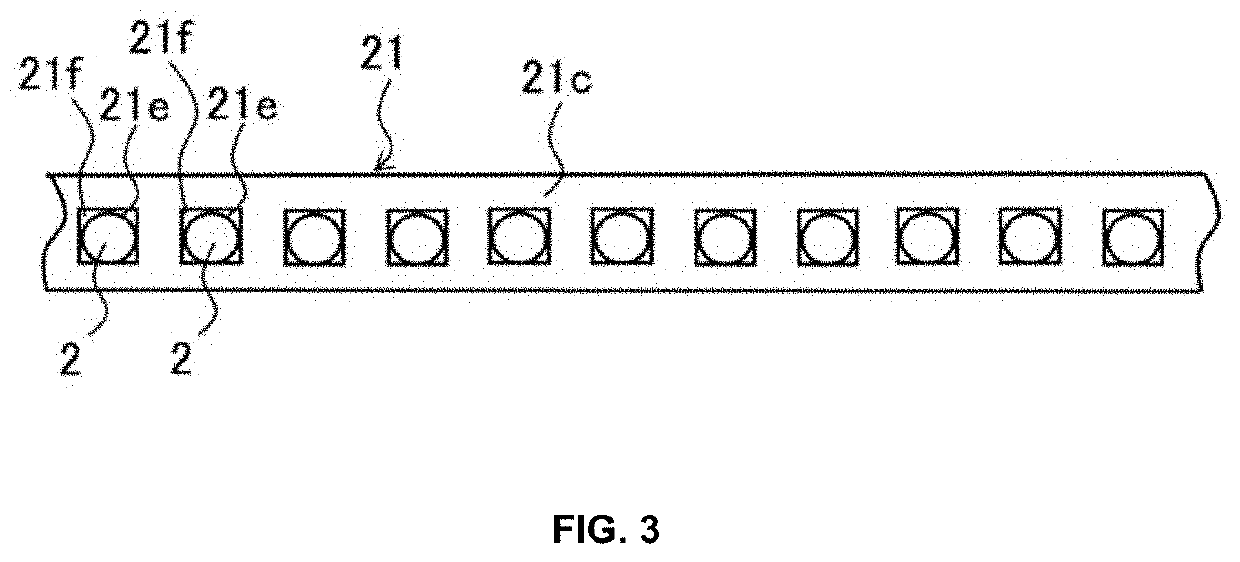
Provided is a method for removing wire-form objects, a device for removing wire-form objects, and a method for processing electronic / electrical apparatus component waste, which can efficiently sort wire-form objects from sorting target objects having various shapes. The method for removing wire-form objects includes: arranging a plurality of filters 3 in a vibrating sieve machine 1 such that the filters 3 are adjacent to each other so as to partially overlap with each other in a feed direction of a raw material, each of the filters including a plurality of rods 2 extending at distances in the feed direction and a beam portion 21 for supporting the plurality of rods 2 at one ends 2a of the plurality of rods 2, the other ends 2b of the plurality of rods 2 being free ends; and feeding a raw material containing at least wire-form objects and plate-form objects into the vibrating sieve machine 1; and vibrating the filters 3 to sieve out the wire-form objects toward an under-sieve side of the vibrating sieve machine 1.

Description

FIELD OF THE INVENTION[0001]The present invention relates to a method for removing wire-form objects, a device for removing wire-form objects, and a method for processing electronic / electrical apparatus component scrap. More particularly, it relates to a method for removing wire-form objects, a device for removing wire-form objects, and a method for processing electronic / electrical apparatus component waste, which are suitable for recycling of used electronic / electrical apparatuses.BACKGROUND OF THE INVENTION[0002]There is known a device for selectively removing particular foreign matters, for example, wire-form objects, from objects to be sorted. For example, Japanese Patent Application Publication No. 2015-150505 A (Patent Literature 1) describes an example of a sorting device for sorting a target sorting object from a mixture of long materials by sorting with a vibrating screen and sorting with an air stream.[0003]Further, from the viewpoint of resource conservation in recent yea...

Claims


Application Information

Patent Timeline
IPC IPC(8): B07B1/12B07B1/36B09B3/00
CPCB07B1/12B09B3/00B07B1/36B09B5/00B07B13/04B07B13/003Y02P10/20
Inventor AOKI, KATSUSHITAKEDA, TSUBASA
Owner JX NIPPON MINING& METALS CORP
Learn More