
Microfluidic systems incorporating integrated optical waveguides

Inactive Publication Date: 2006-08-03
COLORADO SCHOOL OF MINES
View PDF97 Cites 35 Cited by
  • Summary
  • Abstract
  • Description
  • Claims
  • Application Information

AI Technical Summary

Benefits of technology

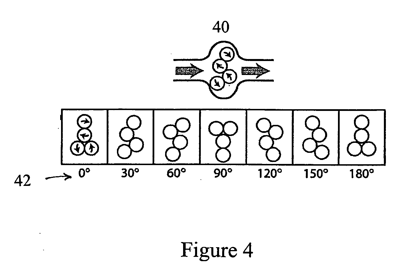
[0010] One embodiment of the current invention overcomes the scaling limitations of conventional scanning systems while avoiding alterations to the basic laser mode through the utilization of a diode laser bar for the rapid manipulation of multiple particles in the microfluidic systems. This technique allows the control of objects within a trap line created by the diode laser bar focused onto the sample. By using this technique in a microfluidic system incorporating this device, particles may be manipulated in static and flowing environments using a simple mask at the intermediate image plane. This simple one to one control scheme, as well as angling the beam with respect to the channel enables efficient particle and cell sorting at the micro scale. Through the use of diode laser bars, vast arrays of independently-controlled particles and cells can be maneuvered.
[0011] The complete integration of microparticle detection and sorting in the microfluidic systems is possible using the methods and devices of the present invention. These techniques rely on direct waveguide writing using ultra-fast laser pulses, which produce index of refraction changes within materials. Tightly focusing a femtosecond pulsed laser into a block of fused silica produces a material change that locally increases the index of refraction of the glass. By translating the focus through the glass, a line of higher refractive index surrounded by a lower index material—a waveguide—is created. The waveguide transports single or multi-mode beams of light with minimal loss. Utilizing waveguides in coordination with microfluidic channels, fluorescence is induced in particles above the individual output of the guide. Because the excitation light is localized at the output of the waveguide, only colloidal particles or cells occupying a position directly above the output spot will fluoresce. Placing a band pass or rejection band filter in front of a CCD camera enables the excitation wavelength to be blocked, while detecting the emission from a particle located at the waveguide output. In this way, distinct flashes of a specific wavelength are produced as individual fluorescent particles pass over the waveguide outputs. This technique provides a parameter with which to sort particles that is compatible with many standard, well-developed fluorescent-labeling protocols. A particle can be sorted into a desired output stream by positioning it with the diode laser bar and identifying its fluorescence characteristics at the release point for the output with the waveguide.

Problems solved by technology

But scanning laser optical trapping (SLOT) is restricted by the piezoelectric elements that translate the mirror and is therefore limited in scalability in applications such as microfluidics.
Optical vortices are single beam optical gradient force traps created by focusing helical modes of light, and are limited by their great sensitivity to aberrations.

Method used


Image

  • Microfluidic systems incorporating integrated optical waveguides
  • Microfluidic systems incorporating integrated optical waveguides
  • Microfluidic systems incorporating integrated optical waveguides

Examples


Embodiment Construction

[0025] The present invention is drawn to microfluidic systems that manipulate, isolate and sort particulate such as colloidal particles, cells, cell organelles and the like, in a portable micro-scale platform that allows for trapping, manipulation, isolation and sorting of the particulate, with convenient signal acquisition, interpretation, and real time feedback and to methods of manufacturing and using these systems.

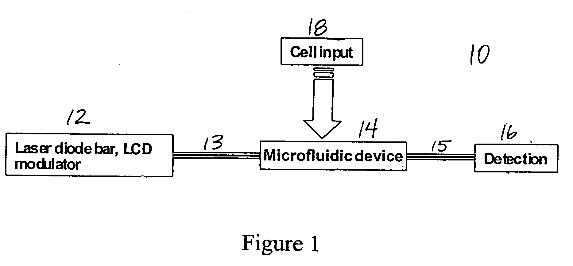
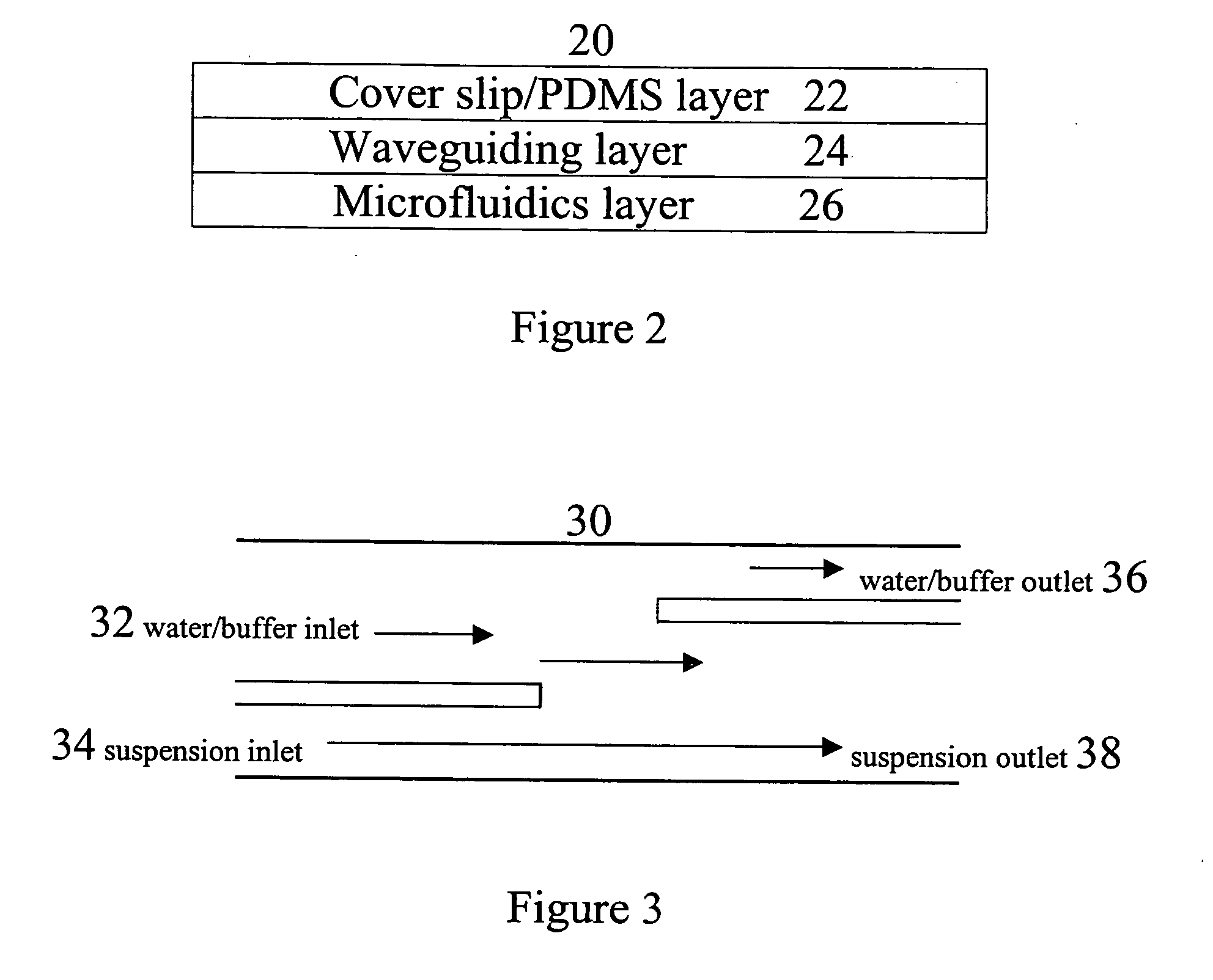
[0026] Referring to FIG. 1, a basic system schematic of a microfluidic system 10 capable of cell sorting, and optical interrogation of individual cells, is illustrated. The microfluidic system 10 includes a light source 12, which, in one preferred embodiment, is a laser diode bar with an LCD modulator. The light source 12 may include a single, compact solid state laser diode, which, in one embodiment, is a one watt diode. However, as will be understood, the light source 12 may include other devices, including multiple laser diodes, having various power consumption. Th...


PUM


Abstract

The invention provides microfluidic systems incorporating optical waveguides integrated, which can be used to optically interrogate particulate such as cells flowing through the system. The waveguides within these systems may be arranged to form optical traps, which may be used to power pumps and valves in the microfluidic systems, to trap and interrogate particles within these systems, and to sort trapped particles into different channels of microfluidic flow.

Description

CROSS REFERENCE TO RELATED APPLICATION [0001] This application claims priority under 35 U.S.C. § 119(e) to U.S. Provisional Patent Application Ser. No. 60 / 642,817 filed Jan. 10, 2005, which is incorporated herein, in its entirety, by this reference.GOVERNMENT INTEREST [0002] This invention was made with Government support under grant number R21 EB001722-01 awarded by the National Institutes of Health (NIH). The Government has certain rights in this invention.FIELD OF THE INVENTION [0003] The present invention is directed to microfluidic systems, and, more particularly, to optical waveguides integrated into microfluidic systems, which can be used to optically interrogate particulate such as cells flowing through the system. In addition, a specifically arranged array of waveguides may form optical traps which, when sequentially pulsed, may be used to power pumps and valves in the microfluidic systems and to sort trapped particles into different channels of microfluidic flow. BACKGROUN...

Claims


Application Information

Patent Timeline
IPC IPC(8): G01N21/00
CPCG01N15/1459G01N15/1463G01N21/05G01N21/645G01N2015/149G01N2021/6482G01N2201/0612G01N2021/0346G01N15/1433G01N15/149
Inventor MARR, DAVID W. M.SQUIER, JEFF
Owner COLORADO SCHOOL OF MINES
Learn More