System and method for cleaning and sanitizing foodstuff tanks

a food tank and food technology, applied in water installations, disinfection, construction, etc., can solve the problems of long labor hours, high labor intensity, and long time consumption of workers, and achieve the effect of reducing water use, effectively sanitizing the container, and facilitating liquid solution dispersion

Pending Publication Date: 2021-07-01
HINCK RONALD
View PDF0 Cites 1 Cited by
  • Summary
  • Abstract
  • Description
  • Claims
  • Application Information

AI Technical Summary

Benefits of technology

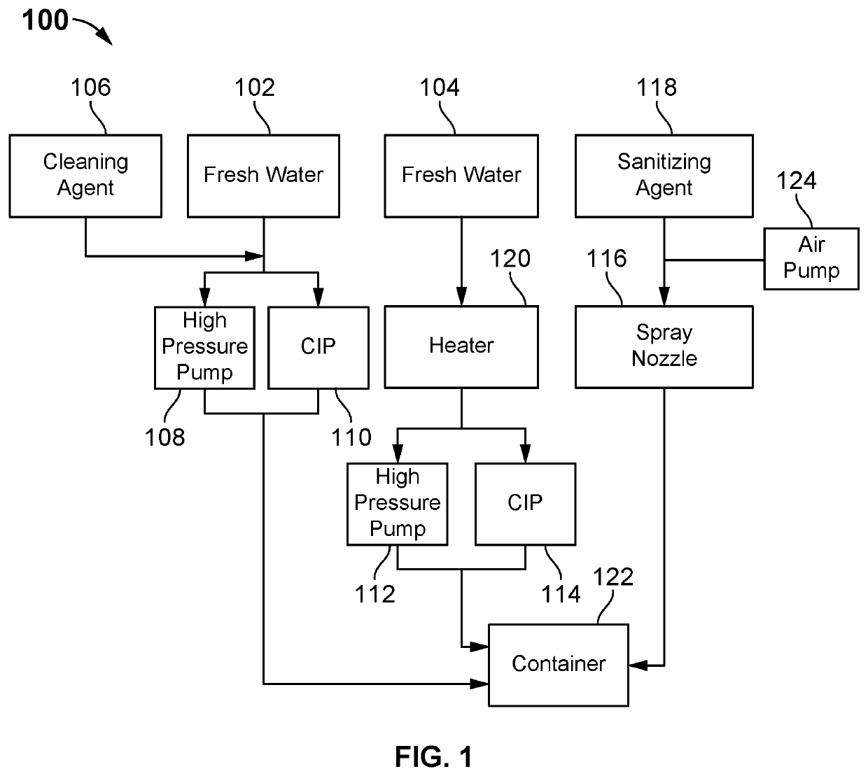
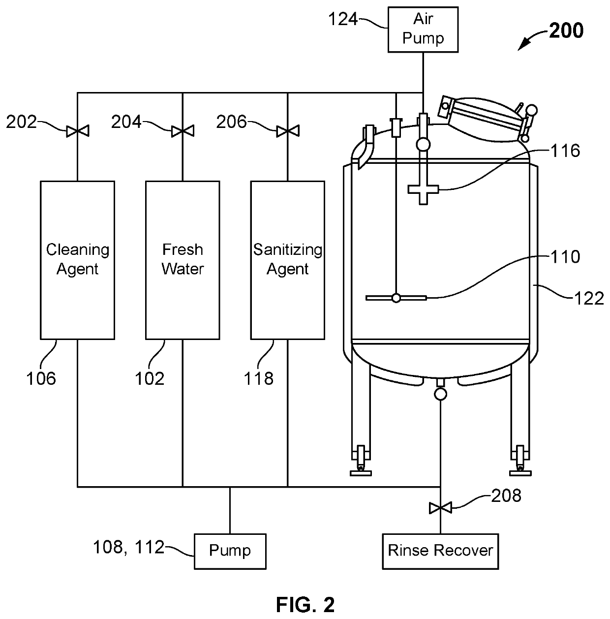
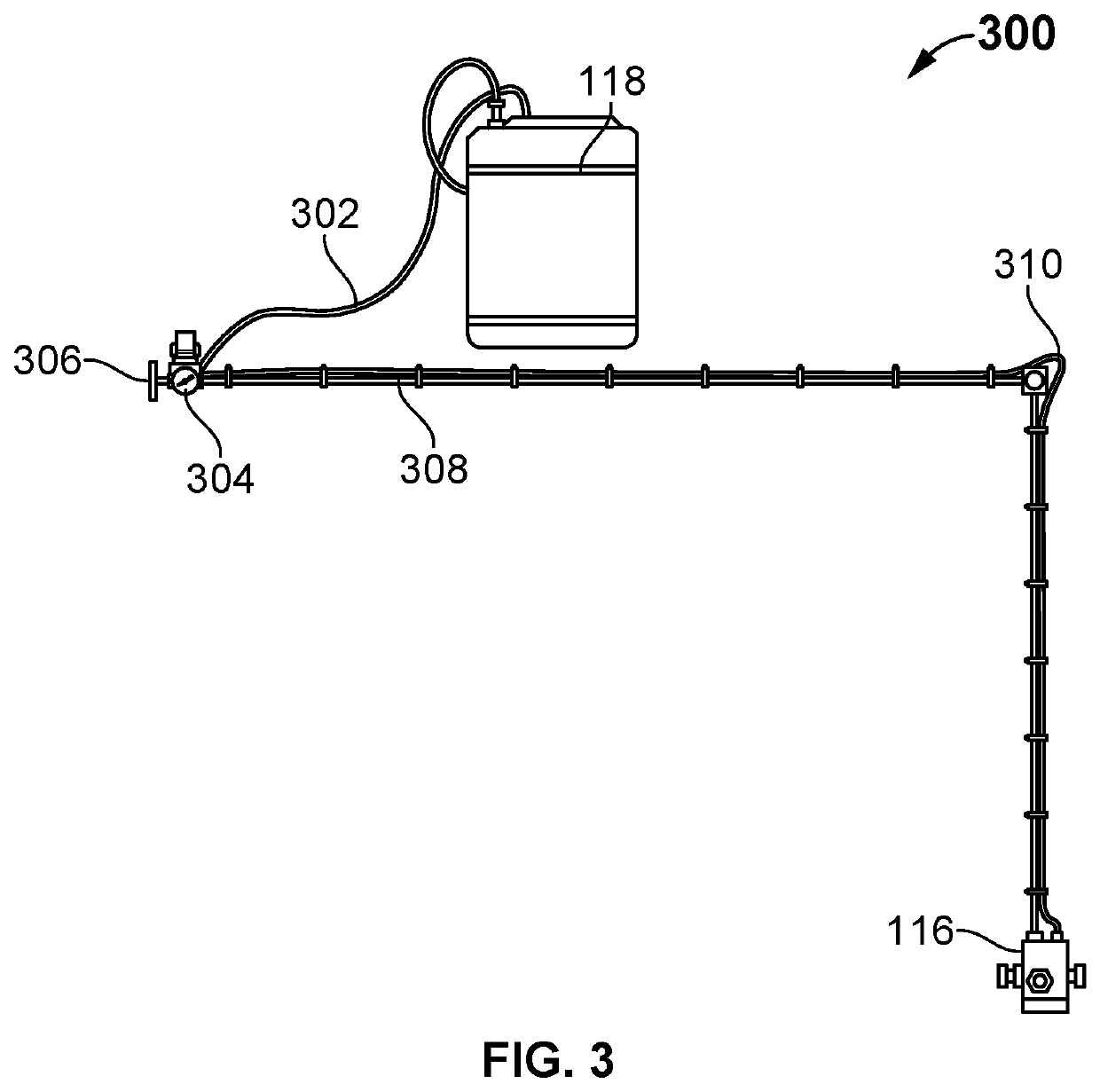
[0022]In one embodiment, the system is used for sanitizing the container using the liquid solution, for example, a sanitizing agent. In one embodiment, the liquid solution is, but not limited to, a sanitizing agent, which is used for a sanitizing process. In one embodiment, the sanitizing agent, chlorine dioxide (ClO2) and peracetic acid (PAA). In one embodiment, at least one spray nozzle is used to facilitate dispersion of the liquid solution, for example, chlorine dioxide (ClO2) and / or peracetic acid (PAA) into a mist / spray for effectively sanitizing the container. In one embodiment, the spray nozzle is fluidly connected to the at least one solution chamber via a line and is securely positioned within the container. The system comprises a nitrogen pump that provides nitrogen that is mixed with the sanitizing agent in a housing at the nozzle concurrently to reduce water use.
[0023]In one embodiment, the system uses at least three solution chambers for storing liquid solutions, which are used for efficiently cleaning, rinsing, and sanitizing the container. In one embodiment, the liquid solution includes at least any one or a mixture of water and a cleaning agent, for example, a caustic cleaner, for cleaning the container. In one embodiment, the liquid solution includes at least any one of a sanitizing agent, for example, chlorine dioxide (ClO2) and / or peracetic acid (PAA) for sanitizing the container. In one embodiment, at least one or more pumps is used for circulating the liquid solutions from the solution chambers to the container via one or more conduits.

Problems solved by technology

Conventional tank cleaning and sanitization is often a long, stringent, hazardous, and labor-intensive task.
Conventional methods of tank and vessel cleaning require operator exposure to dangerous environments, use a relatively high volume of harsh or hazardous chemicals, and also, use a high volume of fresh water.
At modern wineries, these stainless-steel tanks may be cleaned daily, which requires a massive amount of labor hours, especially considering the elements of the tank that require cleaning, which include but are not limited to the fermenter, airlock, bungs, hoses, siphon and any other pieces of equipment that will come in contact with the wine.
These systems generally require extensive mounting or setup within the tanks or containers prior to cleaning, during which workers may be subject to prolonged exposures to the contents being cleaned.
Additionally, existing tank cleaning systems use fluid directing systems that result in random, wasted movement.
However, in these systems, cycle of a nozzle cannot be controlled once activated, thereby increasing the difficulty of focusing on specific areas in need of cleaning.
However, these past ad hoc approaches are laborious, result in large amounts of wastewater, and utilize high amount of chemicals.

Method used


Image

  • System and method for cleaning and sanitizing foodstuff tanks
  • System and method for cleaning and sanitizing foodstuff tanks
  • System and method for cleaning and sanitizing foodstuff tanks

Examples


Embodiment Construction

[0046]The present invention is best understood by reference to the detailed figures and description set forth herein.

[0047]Embodiments of the invention are discussed below with reference to the Figures. However, those skilled in the art will readily appreciate that the detailed description given herein with respect to these figures is for explanatory purposes as the invention extends beyond these limited embodiments. For example, it should be appreciated that those skilled in the art will, in light of the teachings of the present invention, recognize a multiplicity of alternate and suitable approaches, depending upon the needs of the particular application, to implement the functionality of any given detail described herein, beyond the particular implementation choices in the following embodiments described are shown. That is, there are numerous modifications and variations of the invention that are too numerous to be listed but that all fit within the scope of the invention. Also, ...


PUM

PropertyMeasurementUnit
temperatureaaaaaaaaaa
pressureaaaaaaaaaa
lengthaaaaaaaaaa

Abstract

A system and method for cleaning, rinsing, and sanitizing a container is disclosed. The system has a modular trolley having a dolly having at least one wheel, at least one tube coupled to the dolly, wherein the tube has a hollow interior and an inlet end, and wherein the tube has a vertical section located on a back side of the dolly, a chassis coupled to the at least one tube and posited downstream of the dolly, wherein the chassis comprises at least one chassis wheel, a spray nozzle fluidly coupled to an end of the tube on the vertical section, a sanitizing container for storing a sanitizing agent, wherein the sanitization container is supported by the dolly, a sanitization feed hose fluidly coupled to the spray nozzle, a gas source coupled to the inlet end of the tube, a pump in fluid commination with the sanitizing agent chamber, wherein the pump is in fluid communication with a gas; and wherein the gas source, via the tube, introduces the gas to the spray nozzle to mix the sanitizing agent, at pressure, with the gas to disperse the sanitizing agent and gas mixture in the container for sanitizing the container.

Description

CROSS-REFERENCE TO RELATED APPLICATIONS[0001]This application is a continuation in part of U.S. patent application Ser. No. 16 / 776,848 entitled System and Method for Cleaning and Sanitizing Foodstuff Tanks filed Jan. 30, 2020, which itself claims the benefit of U.S. Provisional Application Ser. No. 62 / 798,553 entitled System and Method for Cleaning and Sanitizing Foodstuff Tanks filed on Jan. 30, 2019, the entire contents of each are incorporated herein by reference for all purposes.FIELD OF INVENTION[0002]The present invention generally relates to a system and method for cleaning and sanitizing foodstuff tanks. More specifically, the present invention relates to a system and method for wine holding tanks and fermentation tanks, beer tanks, cider, tanks and spirit tanks.BACKGROUND[0003]Conventional tank cleaning and sanitization is often a long, stringent, hazardous, and labor-intensive task. Conventional methods of tank and vessel cleaning require operator exposure to dangerous env...

Claims


Application Information

Patent Timeline
Patent Type & Authority Applications(United States)
IPC IPC(8): B08B9/08A61L2/26
CPCB08B9/0813A61L2/26A61L2202/122A61L2202/15A61L2/186A61L2202/23B08B2203/007B08B2209/08A61L2202/17A61L2/22A61L2101/06B08B9/093
Inventor HINCK, RONALD
Owner HINCK RONALD
Why Eureka
Try Eureka