A device for measuring blood pressure

a blood pressure and monitoring device technology, applied in the field of physiological signal monitoring system, can solve the problems of poor blood flow, discomfort of the person being measured, heart disease, etc., and achieve the effects of convenient monitoring, improved wear experience, and high accuracy of blood pressure monitoring

Pending Publication Date: 2021-07-08
ACCURATE MEDITECH INC
View PDF0 Cites 1 Cited by
  • Summary
  • Abstract
  • Description
  • Claims
  • Application Information

AI Technical Summary

Benefits of technology

[0005]An objective of the present disclosure is to provide a method and a wearable device for blood pressure monitoring with high measurement accuracy.
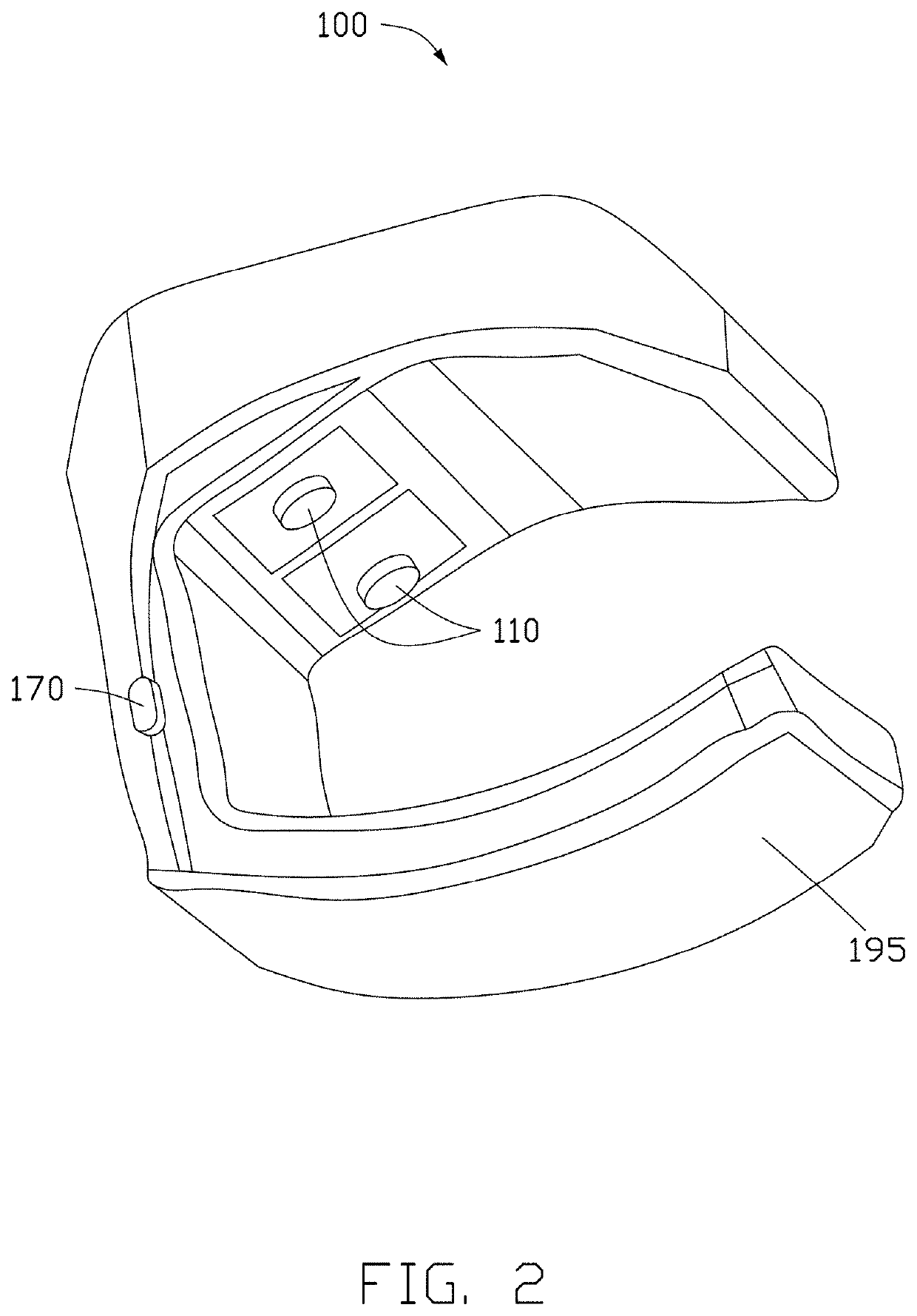
[0022]In a preferred embodiment, the plurality of sensors comprise a mechanical wave sensors, at least one of a plurality of through-holes formed on the housing is conical shaped, and the at least one through-holes enhances reception of the mechanical wave sensor.
[0023]In a preferred embodiment, the device further comprises a contacting material fixedly attached around an opening of the plurality of through-holes to enhance seal tightness between the opening and a skin surface of the user.
[0030]In sum, the device and method according to the various embodiments of the present disclosure utilize pulse transit time and hemodynamic parameters to ensure high accuracy of blood pressure monitoring, improved wearing experience, and convenient monitoring.

Problems solved by technology

If untreated or poorly treated, hypertension may lead to heart disease, poor blood flow, or even stroke.
However, strapping and pumping are required in oscillometric measurements, therefore causing discomfort to the person being measured.
Furthermore, although cuff-less blood pressure measurement may ease discomfort, accuracy of the measurement remains questionable, at least for that several hemodynamic parameters are not taken into consideration in the linear or non-linear regression calculation used in the measurement.

Method used


Image

  • A device for measuring blood pressure
  • A device for measuring blood pressure
  • A device for measuring blood pressure

Examples


Embodiment Construction

[0072]The present invention will now be described more fully hereinafter with reference to the accompanying drawings illustrating various exemplary embodiments of the invention. The present invention may, however, be embodied in many different forms and should not be construed as limited to the embodiments set forth herein. Rather, these embodiments are provided so that this disclosure will be thorough and complete, and will fully convey the scope of the disclosure to those skilled in the art. Like reference numerals refer to like elements throughout.

[0073]The terminology used herein is for the purpose of describing particular embodiments only and is not intended to be limiting of the disclosure. As used herein, the singular forms “a”, “an” and “the” are intended to include the plural forms as well, unless the context clearly indicates otherwise. It will be further understood that the terms “comprises” and / or “comprising,” or “includes” and / or “including” or “has” and / or “having” wh...


PUM


Abstract

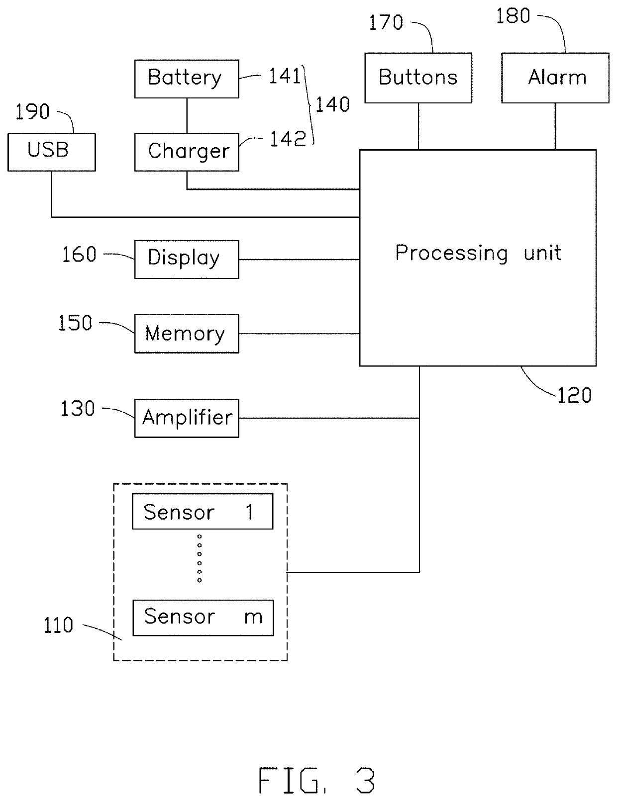
A wearable device for measuring blood pressure comprises a housing with through-holes formed thereon, a processing unit disposed in the housing, a display connected to the processing unit, a plurality of sensors connected to the processing unit, the sensors being configured to transmit at least one physiological signal to the processing unit via the through-holes, and a time delay structure connected between one of the through-holes and one of the sensors and configured to lengthen a path distance between the skin surface and the sensor, wherein the processing unit is configured to determine a systolic arterial pressure and a diastolic arterial pressure by the at least one physiological signal and a Moens-Korteweg (MK) function, and to control the display to display the systolic arterial pressure and the diastolic arterial pressure to be read by the user.

Description

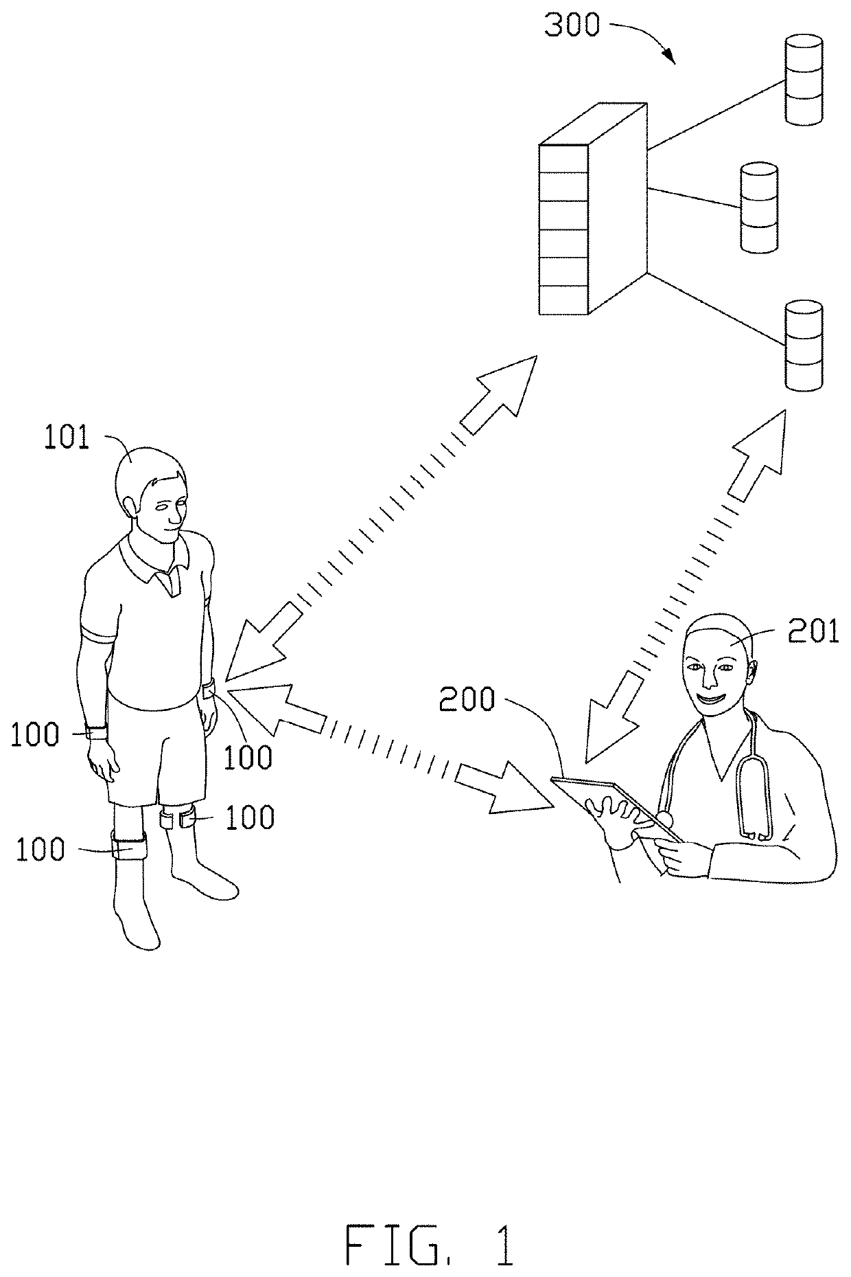
CROSS-REFERENCE TO RELATED APPLICATION[0001]The present application claims priority to U.S. Provisional Application No. 62 / 676,909, filed on May 25, 2018, the entirety of which is incorporated herein by reference.FIELD OF THE INVENTION[0002]The present disclosure relates to a physiological signal monitoring system, and more particularly, to a device that is capable of sensing various types of physiological signals of the user and transmitting the signals to mobile devices and cloud servers for healthcare or diagnostic use by medical professionals.BACKGROUND[0003]Monitoring chronic conditions has been a primary focus in the field of healthcare, not only for the persistency or otherwise long-lasting of the chronic conditions, but also for their potential fatality. One of the common examples of chronic condition is hypertension, which requires accurate and regular monitoring. If untreated or poorly treated, hypertension may lead to heart disease, poor blood flow, or even stroke.[0004]T...

Claims


Application Information

Patent Timeline
Patent Type & Authority Applications(United States)
IPC IPC(8): A61B5/022A61B5/021A61B5/00A61B5/02
CPCA61B5/02233A61B5/02125A61B5/742A61B2562/06A61B5/02007A61B5/0022A61B2562/0219A61B5/0082G16H40/67G16H40/63G16H50/30
Inventor WANG, KUAN JENGUO, CHENG YANHUANG, CHING-HUNG
Owner ACCURATE MEDITECH INC
Why Eureka
Try Eureka