
Fully Deployable And Recapturable Prosthetic Heart Valve

a prosthetic heart valve, fully deployable technology, applied in the field of collapsible prosthetic heart valve implantation, can solve the problems of reducing cardiac efficiency and strain on the heart muscle, leaking blood between the native valve annulus, and affecting the operation of the prosthetic heart valv

Pending Publication Date: 2021-07-08
ST JUDE MEDICAL CARDILOGY DIV INC
View PDF2 Cites 1 Cited by
  • Summary
  • Abstract
  • Description
  • Claims
  • Application Information

AI Technical Summary

Benefits of technology

The patent describes a heart prosthesis system that includes a heart valve and a suture. The heart valve is made up of a collapsible and expandable stent and a valve assembly. The stent has openings around its aortic end and the suture is threaded through these openings. Applying tension to the suture in a direction away from the stent can make the stent's aortic end collapse from its first diameter to a smaller second diameter. The technical effect of this invention is that it provides a way to make a heart valve that can be collapsed for easy placement in the heart and expanded to its original size to ensure proper function.

Problems solved by technology

Inaccurate placement and / or anchoring of the valve may result in the leakage of blood between the prosthetic heart valve and the native valve annulus.
In aortic valves, paravalvular leakage enables blood to flow from the aorta back into the left ventricle during systole, resulting in reduced cardiac efficiency and strain on the heart muscle.
Despite the various improvements that have been made to transcatheter aortic valve repair devices, conventional delivery devices suffer from various shortcomings.
For example, in conventional delivery devices, it may be difficult to correctly position the delivery device at or near the native annulus of the patient and to simultaneously deploy the prosthetic heart valve.
In those instances, when the valve has been improperly deployed or has moved to an improper position after being fully deployed, the prosthetic heart valve would need to be entirely removed from the patient.
Removing a fully deployed prosthetic heart valve requires invasive surgery and greatly increases the risk to the patient.

Method used


Image

  • Fully Deployable And Recapturable Prosthetic Heart Valve
  • Fully Deployable And Recapturable Prosthetic Heart Valve
  • Fully Deployable And Recapturable Prosthetic Heart Valve

Examples


Embodiment Construction

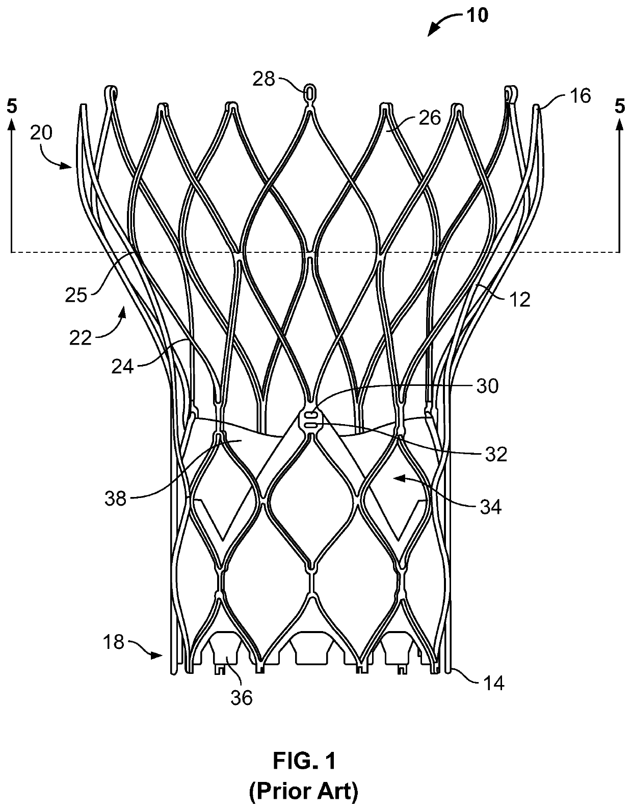
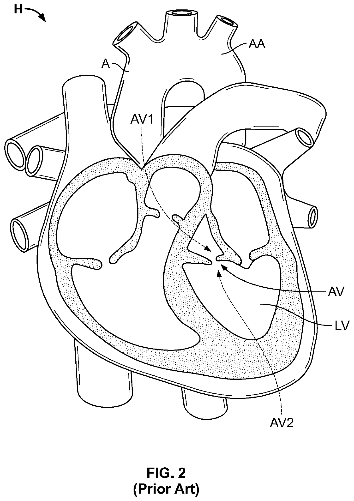
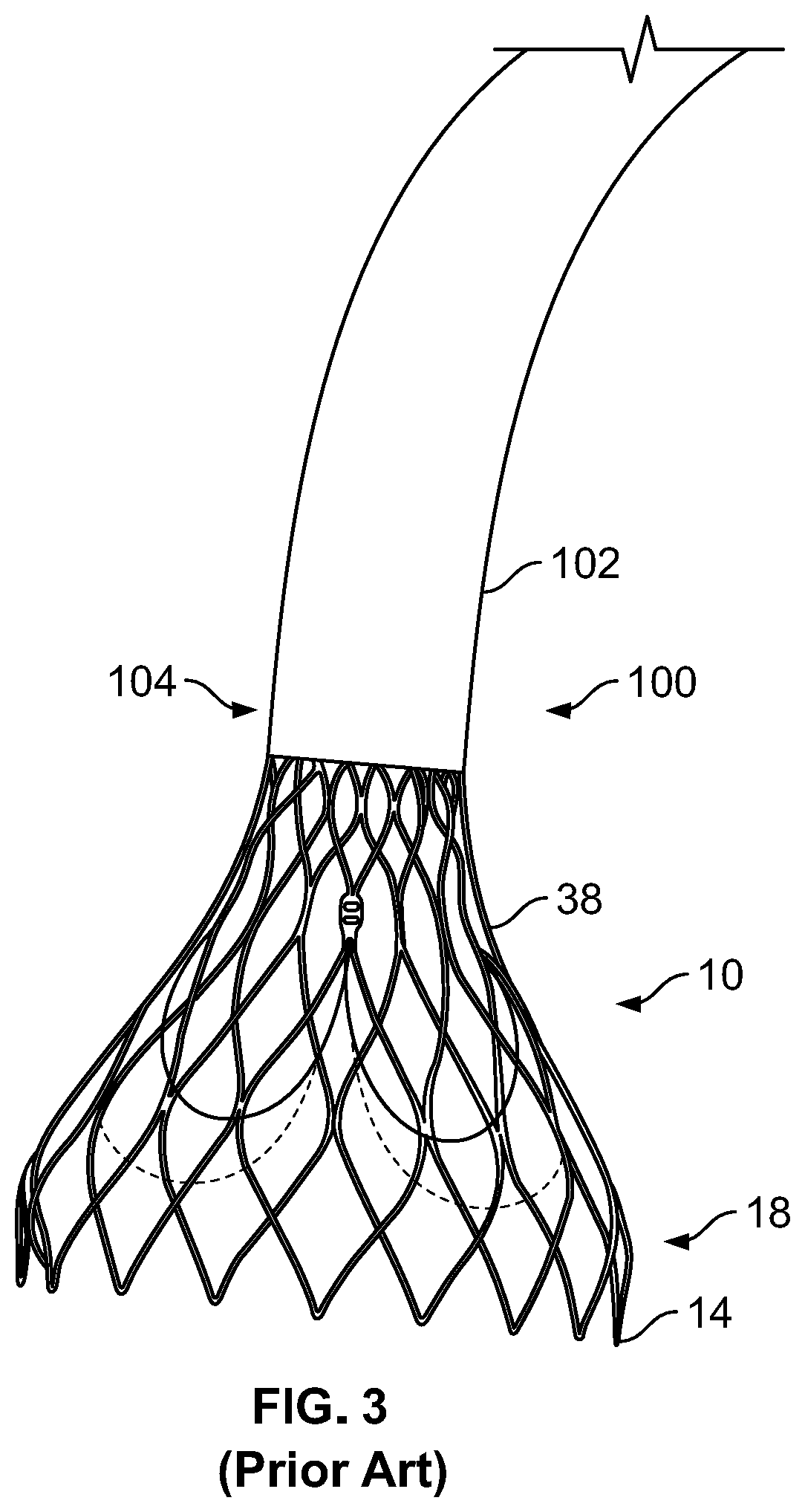
[0020]As used herein in connection with a prosthetic heart valve, the term “inflow end” refers to the end of the heart valve through which blood enters when the heart valve is functioning as intended, and the term “outflow end” refers to the end of the heart valve through which blood exits when the heart valve is functioning as intended. As used herein in connection with a prosthetic heart valve, the term “proximal” refers to the inflow end of the heart valve or to elements of the heart valve that are relatively close to the inflow end, and the term “distal” refers to the outflow end of the heart valve or to elements of the heart valve that are relatively close to the outflow end. When used in connection with devices for delivering a prosthetic heart valve into a patient, the terms “proximal” and “distal” are to be taken as relative to the user of the delivery devices. “Proximal” is to be understood as relatively close to the operator, and “distal” is to be understood as relatively ...


PUM


Abstract

A heart prosthesis system may include a prosthetic heart valve and a length of suture. The prosthetic heart valve may include a collapsible and expandable stent and a valve assembly mounted within the stent. The stent may have an aortic end, an annulus end, and a plurality of openings arranged circumferentially around the aortic end, the aortic end having a first diameter in an expanded condition. The length of suture may be threaded through the openings such that tension applied to the length of suture in a direction away from the stent may collapse the aortic end of the stent from the first diameter to a second diameter less than the first diameter.

Description

CROSS-REFERENCE TO RELATED APPLICATIONS[0001]The present application claims the benefit of the filing date of U.S. Provisional Patent Application No. 62 / 958,456 filed Jan. 8, 2020, the disclosure of which is hereby incorporated by reference.BACKGROUND[0002]The present invention relates to collapsible prosthetic heart valve implantation, and more particularly, to apparatus and methods for ensuring proper positioning and stabilization of the prosthetic heart valve during implantation.[0003]Prosthetic heart valves that are collapsible to a relatively small circumferential size can be delivered into a patient less invasively than valves that are not collapsible. For example, a collapsible valve may be delivered into a patient via a tube-like delivery apparatus such as a catheter, a trocar, a laparoscopic instrument, or the like. This collapsibility can avoid the need for a more invasive procedure such as full open-chest, open-heart surgery.[0004]Collapsible prosthetic heart valves typic...

Claims


Application Information

Patent Timeline
IPC IPC(8): A61F2/24
CPCA61F2/2418A61F2250/0012A61F2220/0075A61F2/2436A61F2/2439A61F2/9522
Inventor BLOOMQUIST, ALEX L.VIETMEIER, KRISTOPHER HENRY
Owner ST JUDE MEDICAL CARDILOGY DIV INC
Learn More