

Polishing and loading/unloading component module
- Summary
- Abstract
- Description
- Claims
- Application Information
AI Technical Summary
Benefits of technology
Problems solved by technology
Method used
Image

Examples
Embodiment Construction
[0063]The present invention is described in detail below with reference to the drawings and specific embodiments. The embodiments are implemented on the premise of the technical solution of the present invention, and a detailed implementation mode and specific operation process are given, but the protection scope of the invention is not limited to the following embodiments.
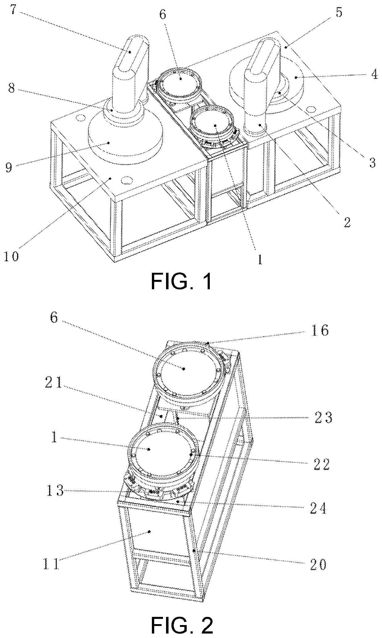
[0064]The embodiment provides a polishing and loading / unloading component module for CMP equipment. The polishing and loading / unloading component module comprises one loading / unloading module and two polishing modules, with the layout shown in FIG. 1, including a first loading / unloading position 1, a first polishing head rotating shaft 2, a first polishing head 3, a first polishing pad 4, a first fixed platform 5, a second loading / unloading position 6, a second polishing head rotating shaft 7, a second polishing head 8, a second polishing pad 9, and a second fixed platform 10.
[0065]The polishing pad, the polishing...
PUM
 Abstract
Description
Claims
Application Information