Optical system of near-eye see-through head-mounted display

a technology of optical system and display, applied in optics, instruments, lenses, etc., can solve the problems of large exit pupil aperture and short focal length, user cannot walk around and interact with the outside world at the same time, and achieve large viewing angle, large viewing angle, and long focal length. , to achieve the effect of ultra-large viewing angle and high luminous brightness

Active Publication Date: 2021-07-08
TAPUYIHAI SHANGHAI INTELLIGENT TECH CO LTD
View PDF0 Cites 1 Cited by
  • Summary
  • Abstract
  • Description
  • Claims
  • Application Information

AI Technical Summary

Benefits of technology

The present invention is an optical system for a near-eye see-through head-mounted display. It includes a prism that reflects and images an image generated by a micro image display. The prism is attached to a first lens and a second lens, which are also attached to the micro image display. The first and second lenses are free-form lenses, meaning they have a uniform thickness. This optical system allows the user to see both the real external environment through the first and second lenses and the image generated by the micro image display. The technical effect of this invention is to improve the convenience and usability of the see-through head-mounted display by integrating a prism with a more comfortable and feasible optical system.

Problems solved by technology

For the purpose of enhancing immersion and obtaining a large viewing angle, the current VR head-mounted display products are large and heavy, so the user cannot walk around and interact with the outside world when wearing VR displays.
In addition, AR head-mounted display products have a small viewing angle, and the AR head-mounted display products also have large volume and thick lenses.
Because the viewing angle, exit pupil aperture, and focal length of the optical system are mutually restrictive, achieving a large viewing angle, large exit pupil aperture and short focal length simultaneously are quite difficult.
At this time, the prisms or lenses used will have dispersion issues and the entrance pupil distance is not large, so it is not compatible with glasses.
If it is designed to have a large entrance pupil distance, the volume and weight of the head-mounted display will increase exponentially, and multiple refractions and reflections reduce the utilization of light energy.
The resolution of the micro liquid crystal display is difficult to be high, and the area and brightness is limited (because the temperature is considered), the cost is also very high.
In addition, there are issues of two lenses asymmetry, material selection, injection molding shrinkage during manufacturing, thermal expansion, gluing, and large weight and volume of solid materials.
Each refraction increases the risk of image distortion in the image emitted by the micro image display, and the refractive index of the prism with three free-form surfaces is not equal to 1, so in addition to the previous two refractions and two reflections, the light in the free-form prism, due to the fact that the material is unevenly distributed and the refractive index at each point is not equal to 1, will be tens of thousands of times of refractions and reflections on the image light, which seriously affects the imaging quality.
In addition, prism with a free-form surface is generally made of glass, and this device is formed by splicing multiple prisms with free-form surfaces, which causes the entire device to be too heavy.
Finally, since the cost and priding mirror technology are considered for the design of the prism with free-form surfaces, it is impossible to design the three optical free-form surfaces as free-form surfaces that can eliminate the image distortion, so that when the light encounters a free-form surface and is refracted, it will cause field curvature or spherical aberration and other aberrations, so the imaging quality of this device is poor.
The improvement of image quality generally requires the use of a lot of correction technology, such as aberration correction or distortion correction etc., therefore, the manufacturing cost is increased.

Method used


Image

  • Optical system of near-eye see-through head-mounted display
  • Optical system of near-eye see-through head-mounted display
  • Optical system of near-eye see-through head-mounted display

Examples


Embodiment Construction

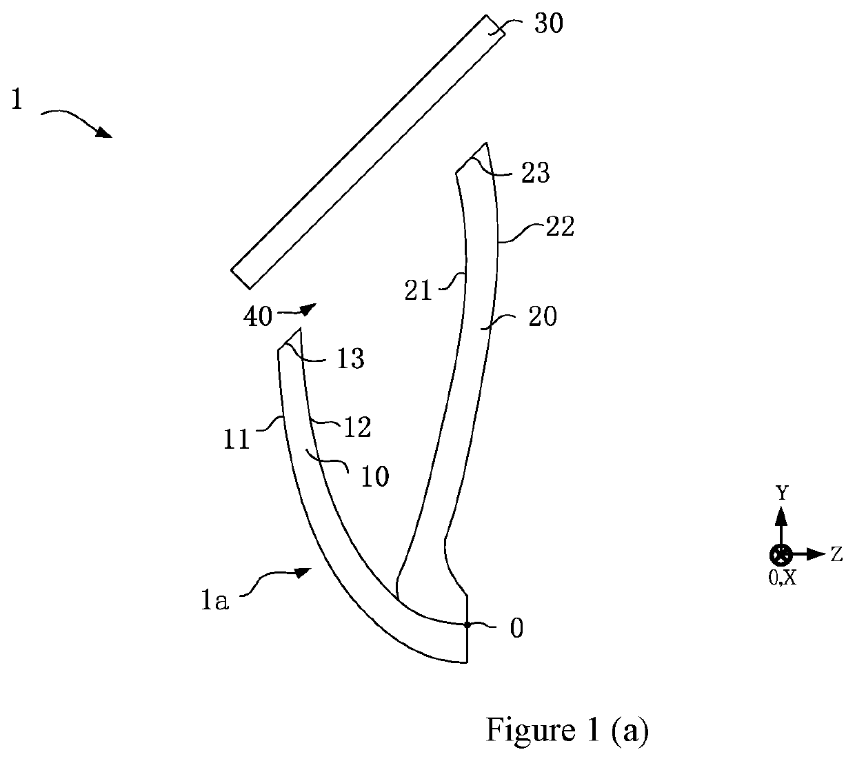
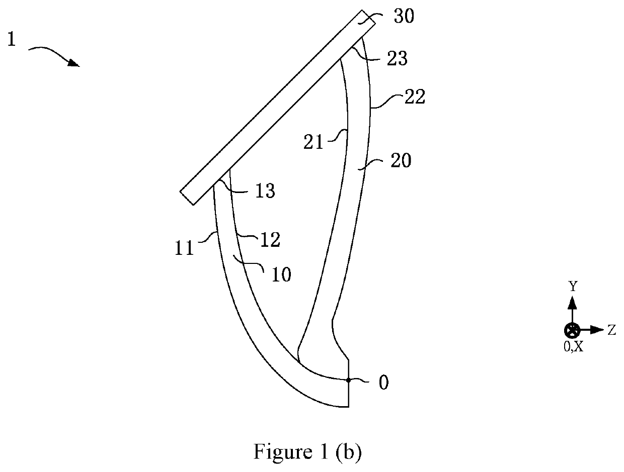
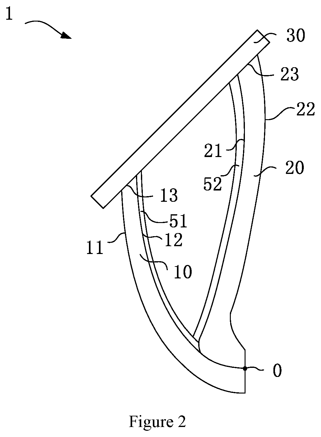
[0024]In order to make the purpose, technical features and advantages of the present invention more understandable to those skilled in the art and to implement the present invention, the technical features and embodiments of the present invention are specifically illustrated in accompany with the drawings, and the preferred embodiment is listed for further illustration. The drawings listed in the following are schematic representations related to the features of the present invention, and they are not needed to be completely drawn according to the actual situation. The description of the embodiment of the present invention involves technical issues that are well known to those skilled in the art, and will not be stated again.

[0025]The coordinate system described in the description of the embodiments and the reference numbers of the drawings in the specification is a Cartesian coordinate system, that is, a three-axis (X, Y, Z) orthogonal coordinate system, and a right-handed coordina...


PUM

PropertyMeasurementUnit
thickaaaaaaaaaa
reflectivityaaaaaaaaaa
refractive indexaaaaaaaaaa

Abstract

The invention discloses an optical system of near-eye see-through head-mounted display, comprising a first lens, a second lens and a micro image display, the first lens and the second lens are attached to the micro image display, and the first lens and the second lens are free-form lenses with a uniform thickness. The architecture of the optical system of near-eye see-through head-mounted display provided by the present invention can not only reduce the number of times the light is refracted in the architecture of the optical system, but also eliminate the aberration of the light emitted by the micro image display in all directions, making the images be viewed from all directions and angles with no aberration.

Description

BACKGROUND OF THE INVENTION1. Field of the Invention[0001]The invention provides an optical system of near-eye see-through head-mounted display, and more particularly, an optical system of near-eye see-through head-mounted display with an off-axis double reverse free-form surface with an ultra-large viewing angle.2. Description of the Related Art[0002]At present, virtual reality (VR) and augmented reality (AR) head-mounted displays are developing rapidly. For the purpose of enhancing immersion and obtaining a large viewing angle, the current VR head-mounted display products are large and heavy, so the user cannot walk around and interact with the outside world when wearing VR displays. In addition, AR head-mounted display products have a small viewing angle, and the AR head-mounted display products also have large volume and thick lenses. Because the viewing angle, exit pupil aperture, and focal length of the optical system are mutually restrictive, achieving a large viewing angle, ...

Claims


Application Information

Patent Timeline
Patent Type & Authority Applications(United States)
IPC IPC(8): G02B27/01G02B25/00G02B3/02G02B1/04
CPCG02B27/0172G02B25/001G02B2003/0093G02B1/041G02B3/02G02B17/0816G02B2027/0132G02B2027/0178
Inventor WEI, RONGJIE
Owner TAPUYIHAI SHANGHAI INTELLIGENT TECH CO LTD
Why Eureka
Try Eureka