
Microcatheter

a micro-catheter and micro-screw technology, applied in the field of micro-catheters, can solve the problems of severe consequences of interruption or failure of interventional surgery, and achieve the effects of improving the torque control force of the micro-catheter, improving the traversing, traceability and flexibility of the micro-catheter

Active Publication Date: 2021-07-15
ORBUSNEICH MEDICAL SHENZHEN CO LTD
View PDF6 Cites 2 Cited by
  • Summary
  • Abstract
  • Description
  • Claims
  • Application Information

AI Technical Summary

Benefits of technology

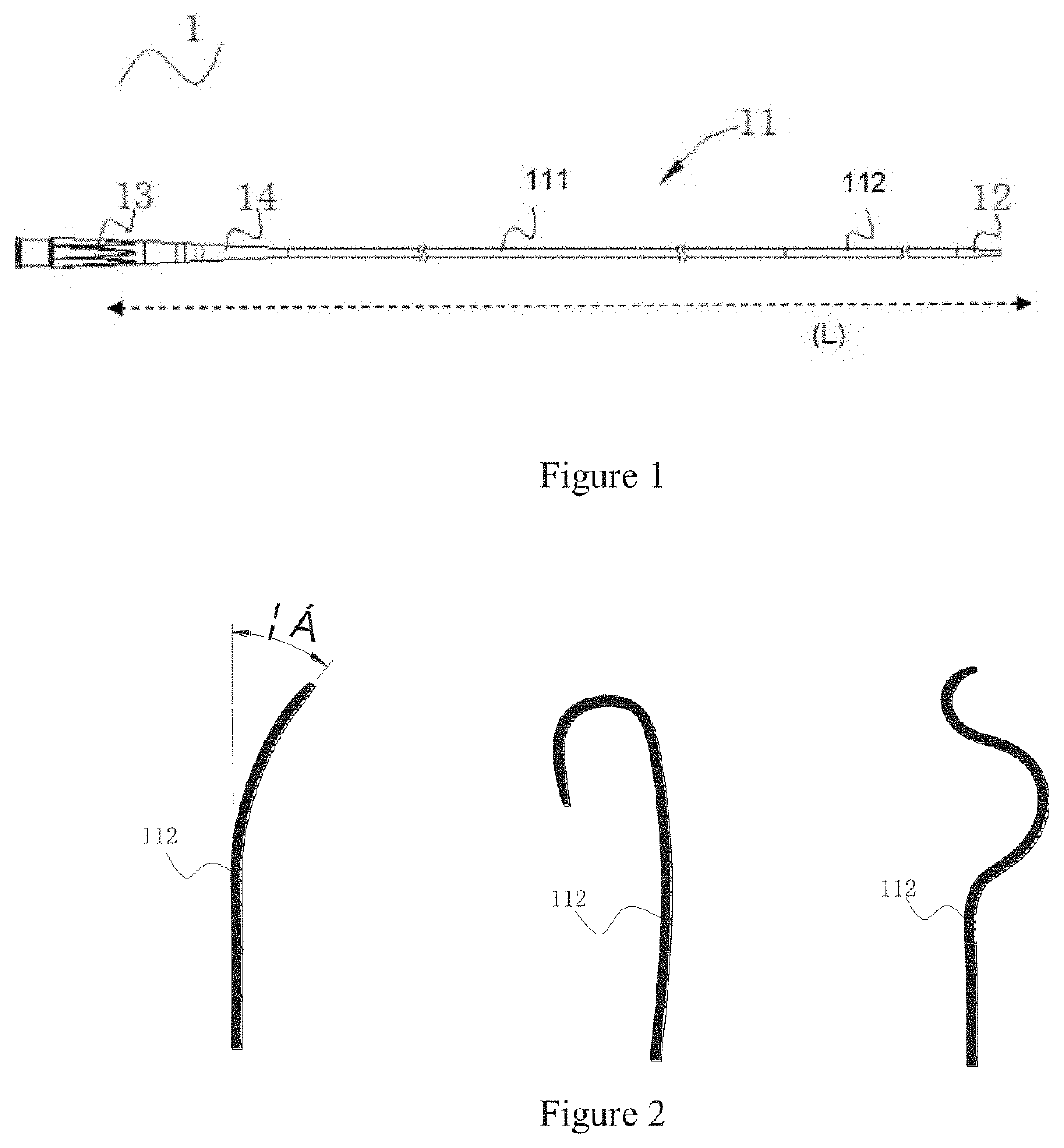
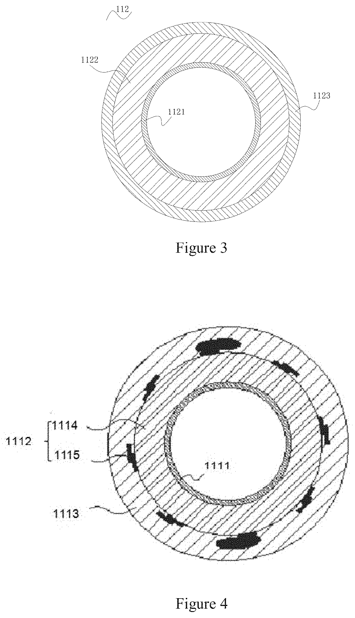
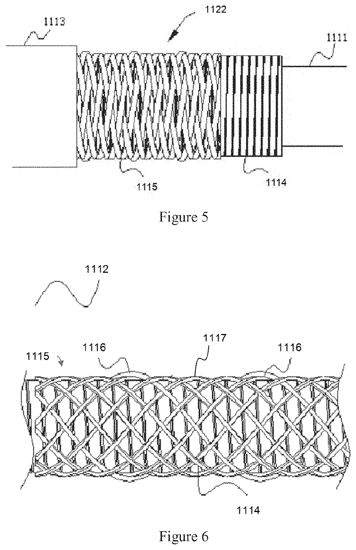
The present invention provides a microcatheter with a flexible and adjustable distal end that can reach bifurcation lesions of the coronary artery. The catheter body has a multilayer structure with a decreasing rigidity from the proximal end to the distal end, and a spiral corrugated tube with a decreasing thickness and increasing distance between wave crests. The catheter body is designed to have a sufficient torsional pushing force and supporting force to improve the torque control force and traverse through the coronary arteries, and to enhance flexibility and reduce complications during a medical procedure.

Problems solved by technology

The existing microcatheter cannot smoothly enter the branch of the coronary artery after entering the main branch of the coronary artery, which affects the guidewire, a dilatation balloon catheter or a stent system to reach the lesion site, resulting in the severe consequences of the interruption or failure of the interventional surgery.

Method used


Image

  • Microcatheter
  • Microcatheter
  • Microcatheter

Examples


Embodiment Construction

[0059]The present invention will now be described more fully hereinafter with reference to the accompanying drawings, in which exemplary embodiments of the invention are shown. This invention may, however, be embodied in many different forms and should not be construed as limited to the embodiments set forth herein. Rather, these embodiments are provided so that this disclosure will be thorough and complete, and will fully convey the scope of the invention to those skilled in the art. Like reference numerals refer to like elements throughout.

[0060]The terminology used herein is for the purpose of describing particular embodiments only and is not intended to be limiting of the invention. As used herein, the singular forms “a”, “an” and “the” are intended to include the plural forms as well, unless the context clearly indicates otherwise. It will be further understood that the terms “comprises” and / or “comprising,” or “includes” and / or “including” or “has” and / or “having” when used he...


PUM

PropertyMeasurementUnit
Angleaaaaaaaaaa
Angleaaaaaaaaaa
Linear resolutionaaaaaaaaaa

Abstract

The present invention discloses a microcatheter, with tubular structure, comprising a catheter body, a sharp portion disposed at a distal end of the catheter body, the catheter body comprises: a inner layer with a hollow lumen; a tubular intermediate layer wrapped outside the inner layer, comprising a spring layer and a braid above the spring layer, the braid extending longitudinally along a part of the spring layer; and a tubular outer layer, wrapped outside the intermediate layer; the part of the spring layer which is not wrapped by the braid is bent at a certain angle along a longitudinal axis of the catheter body. The catheter body of the microcatheter of the invention is configured to have a multilayered structure, and the braid is only wrapped on spring layer near to the proximal end; the part of the spring layer not wrapped by the braid can be bent at a corresponding angle to adapt to an angle between the main branch and the branch of the coronary artery, to make sure that the microcatheter can reach the bifurcation lesions of the coronary artery.

Description

CROSS-REFERENCE TO RELATED APPLICATIONS[0001]The present application is a national phase of Ser. No. PCT / CN2018 / 085444 filed May 3, 2018, the entire contents of which are incorporated herein by reference, and which claims priority to and the benefit of Chinese Patent Application No. 201810404958.5 filed Apr. 28, 2018.BACKGROUND OF THE INVENTION1. Field of the Invention[0002]This invention relates to the field of medical apparatus and instruments, and particularly to a microcatheter that is capable of bending to approximate a side branch.2. Description of the Related Art[0003]In clinic, in order to improve a success rate of a guide wire passing through blood vessels during an interventional surgery, the microcatheter is usually used in combination with the guide wire. The microcatheter can provide support to the guide wire and provide a passage for the guide wire to pass through the blood vessels.[0004]According to the statistics of existing interventional treatment cases, it is foun...

Claims


Application Information

Patent Timeline
IPC IPC(8): A61M25/00A61M25/06
CPCA61M25/0021A61M25/0045A61M2025/0042A61M25/06A61M25/0053A61M25/008A61M25/01A61M25/0662A61M2025/0035A61M25/005A61M25/0054A61M25/0144
Inventor GUO, LIXIAZHANG, PENGTAO
Owner ORBUSNEICH MEDICAL SHENZHEN CO LTD
Learn More