Glue-Down Decorative Floor Covering System

a decorative floor covering and glue-down technology, applied in the direction of flooring, coatings, synthetic resin layered products, etc., can solve the problem of clicking lock between tiles

Active Publication Date: 2021-07-15
I4F LICENSING NV
View PDF0 Cites 2 Cited by
  • Summary
  • Abstract
  • Description
  • Claims
  • Application Information

AI Technical Summary

Benefits of technology

[0014]It is favourable that the first end surface and/or the second end surface is/are provided with at least one glue collecting cavity, in particular at least one glue collecting groove. This glue collecting groove(s) preferably extend(s) in a direc...

Problems solved by technology

This leads to a click-t...

Method used


Image

  • Glue-Down Decorative Floor Covering System
  • Glue-Down Decorative Floor Covering System
  • Glue-Down Decorative Floor Covering System

Examples


Embodiment Construction

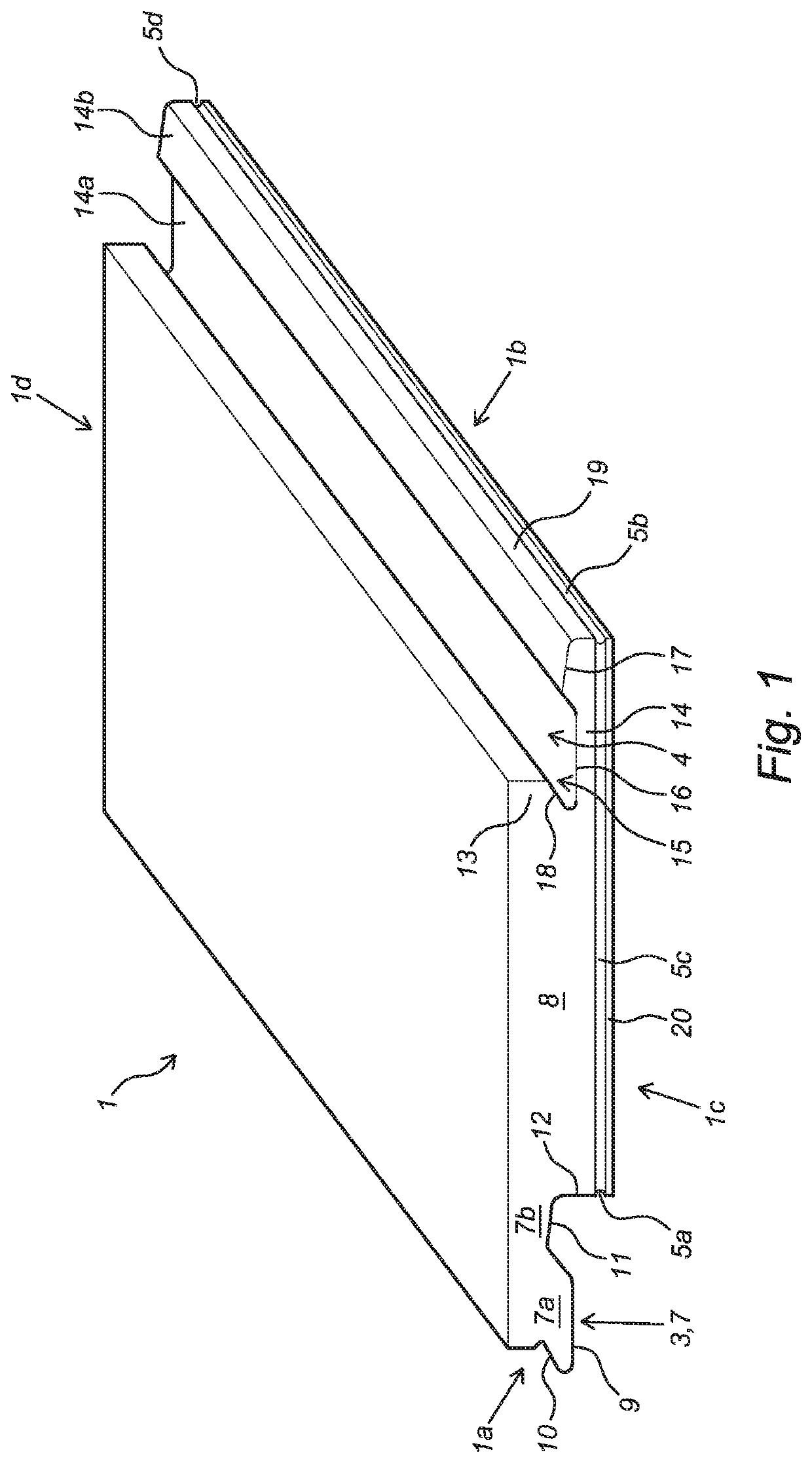
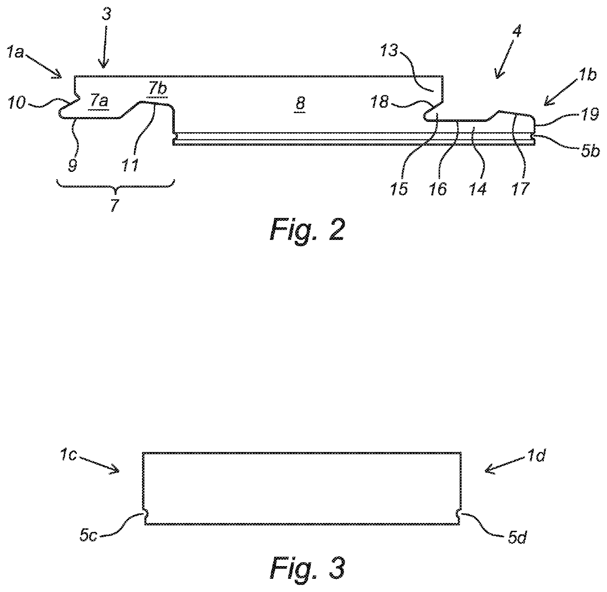
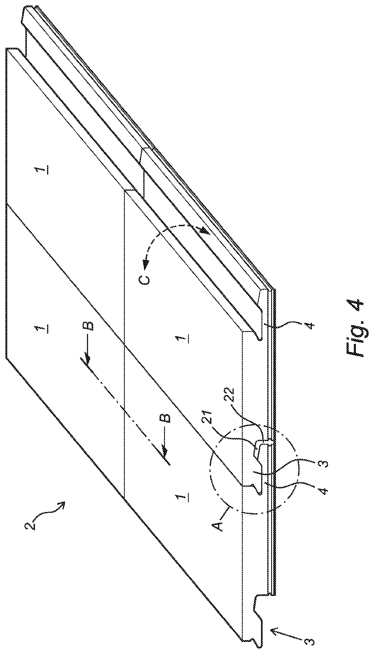
[0032]FIG. 1 shows a perspective view of a rectangular glue-down tile 1 of a glue-down floor covering system 2 (see FIGS. 4-8) according to the invention, FIG. 2 shows a lateral cross-section of the tile according to FIG. 1, and FIG. 3 a longitudinal cross-section of the tile according to FIG. 1. The tile 1 is mechanically interconnectable with two similar tiles for forming said covering 2. The tile 1 comprises a first pair of opposing long edges 1a, 1b, identified as the first edge 1a and the second edge 1b, and second pair of opposing short edges 1c, 1d, identified as the third edge 1c and the fourth edge 1d. The first pair of opposing edges 1a, 1b comprises complementary mechanical coupling parts 3, 4, identified as the male coupling part 3, and the female coupling part 4 to allow the tile 1 to be mechanically coupled with two other tiles 1. The second pair of opposing edges 1c, 1d is free of any mechanical coupling parts, which makes the tile 1 suitable to be mechanically couple...


PUM

PropertyMeasurementUnit
Lengthaaaaaaaaaa
Lengthaaaaaaaaaa
Distanceaaaaaaaaaa

Abstract

The invention relates to a glue-down decorative floor covering system. The invention also relates to a glue-down floor covering realized by a plurality of tiles of the glue-down floor covering system according to the invention. The invention further relates to a tile for use in a glue-down floor covering system according to the invention.

Description

CROSS-REFERENCE TO RELATED APPLICATION[0001]This application claims priority to The Netherlands Patent Application No. 2024630 filed Jan. 9, 2020, the disclosure of which is hereby incorporated by reference in its entirety.BACKGROUND OF THE INVENTIONField of the Invention[0002]The invention relates to a glue-down decorative floor covering system. The invention also relates to a glue-down floor covering realized by interlocking a plurality of tiles of the glue-down floor covering system according to the invention. The invention further relates to a glue-down tile for use in a glue-down floor covering system according to the invention.Description of Related Art[0003]Developed in the 1970s, Luxury Vinyl Plank (LVP) and Luxury Vinyl Tile (LVT) were created as a means to improve upon the realism of sheet vinyl substantially composed of polyvinyl chloride (PVC). Popularity grew exponentially in 2000s as the glue-down construction emerged as a low-cost alternative to HDF / MDF laminate, hard...

Claims


Application Information

Patent Timeline
IPC IPC(8): E04F15/02E04F15/10B32B27/08B32B27/30B32B3/06B32B7/12
CPCE04F15/02038E04F15/105E04F15/02155B32B27/08B32B27/304B32B2419/04B32B7/12E04F2201/0161E04F2201/04B32B2255/10B32B3/06E04F15/107E04F2201/0153E04F2201/023E04F2201/043E04F15/0215E04F2201/07
Inventor BOUCKÉ, EDDY ALBERIC
Owner I4F LICENSING NV
Why Eureka
Try Eureka