Watercraft with Collinear Flotation Elements

a technology of collinear flotation and watercraft, which is applied in the direction of marine propulsion, special-purpose vessels, vessel construction, etc., can solve the problems of lowering top speed, slowing speed, hampered maneuverability, etc., and achieves the effect of minimizing turbulence and water resistance, facilitating maneuverability, and maximizing the change in weight distribution caused by the movement of the pivot axis alon

Active Publication Date: 2021-07-22
BROWN DENNIS BROWN LEE +1
View PDF0 Cites 1 Cited by
  • Summary
  • Abstract
  • Description
  • Claims
  • Application Information

AI Technical Summary

Benefits of technology

[0004]The invention provides an apparatus for water transport, recreation, exercise and sport which is responsive and easy to maneuver. It is herein referred to as a watercraft. The watercraft comprises two or more flotation elements aligned fore and aft, a fore flotation element capable of pivoting about an axis. Adjacent ends of the flotation elements fit together to minimize turbulence and water resistance. The pivoting steering axis of the fore flotation element is tilted aft of vertical toward the watercraft occupants. Pivotal movements of the fore flotation element shifts the transverse center of gravity to maintain balance. The shape of the front flotation element and the angle of the pivot axis effect the amount of weight shift caused by pivotal movements. Changes in weight distribution caused by movement of the pivot axis alone are maximized when the pivot axis of the watercraft is fixed at 45 degrees to the waterline, which is midway between vertical and horizontal. Watercraft use, design and speed are factors which determine the amount of weight shift affect which is desirable, and the pivot axis is therefore set at different angles relative to the waterline in various embodiments of the invention.
[0005]In a preferred embodiment, the watercraft is ridden in a manner similar to riding a bicycle. Riders who are positioned principally above the gunwales of the watercraft can easily maintain balance. When the fore flotation element of the watercraft is turned to the right or left, weight is shifted laterally to the opposite side of the watercraft due to the shape of the fore flotation element and the angle at which it pivots. When the watercraft tilts to either side, a rider is able to avoid tipping over by turning the bow of the watercraft in the same direction that the watercraft is tilting, thereby shifting the transverse center of gravity back toward the center of the watercraft to counter the tipping motion. Balancing in this manner feels familiar to anyone who is proficient at riding a bicycle and it is therefore easy for operators of the watercraft to accomplish. Balance can be easily maintained by the rider when the watercraft is stationary as well as when the watercraft is in motion by making quick steering adjustments.
[0006]In a preferred embodiment, a front rudder projects from the longitudinal center line of the bottom of the fore flotation element. The rudder is rigidly connected to the fore flotation element and the rudder turns with the fore flotation element. The rudder is positioned proximal to the pivotal axis of the fore flotation element which allows for easy and effective steering. A portion of the rudder blade is optionally located aft of the center of said axis. When turning, this counters an initial opposing motion caused by a sweeping movement of the watercraft bow. The position of the rudder also assists the operator when steering the watercraft in a predominately straight path.

Problems solved by technology

However, a wide watercraft hull increases water resistance resulting in slower speeds and hampered maneuverability.
Various watercraft with multiple spaced floats and front or rear steering have been proposed, but these are slow to change course, and water flow is impeded by the configuration of floats and steering elements, resulting in lowered top speeds.
Other attempts at watercraft with narrow single hulls and a high center of gravity had no effective way to stay upright, particularly at low speeds.

Method used


Image

  • Watercraft with Collinear Flotation Elements
  • Watercraft with Collinear Flotation Elements
  • Watercraft with Collinear Flotation Elements

Examples


Embodiment Construction

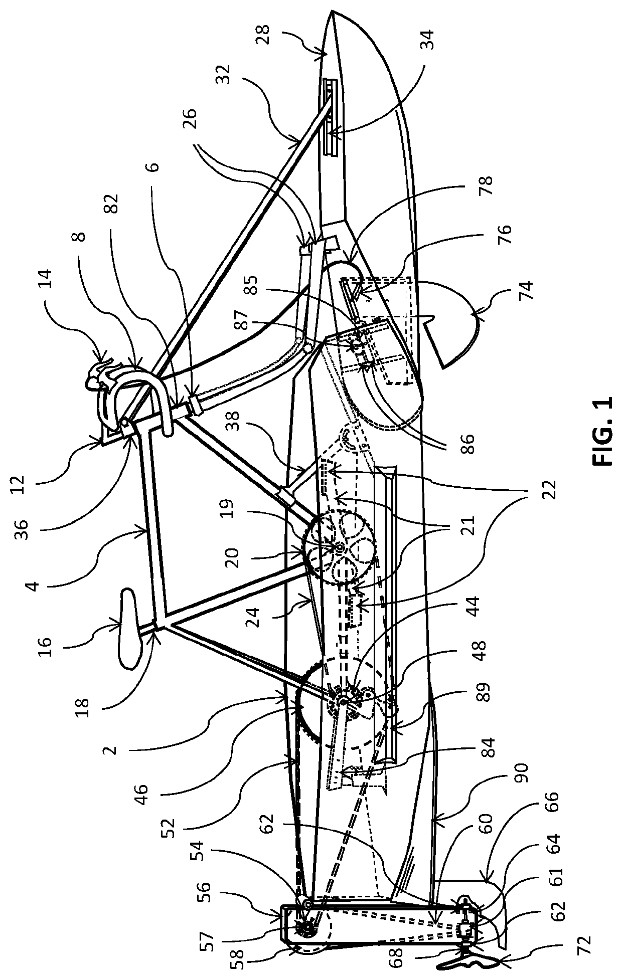
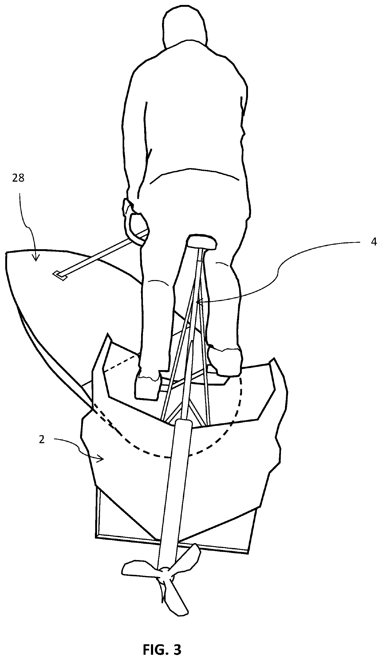
[0017]In a preferred embodiment illustrated in FIG. 1, the invention includes a main flotation element 2 to which a conventional bicycle frame 4 is adjustably attached. The main flotation element 2 is constructed of plastic, or plastic and fiber composite materials, with optional metal reinforcement. A bicycle fork assembly 6 is pivotally attached to the bicycle frame 4. A handlebar 8 with an attached stem riser 12 and a latch release control handle 14 are adjustably attached to the fork assembly 6. A seat 16 and seat post 18 are adjustably attached to the bicycle frame 4.

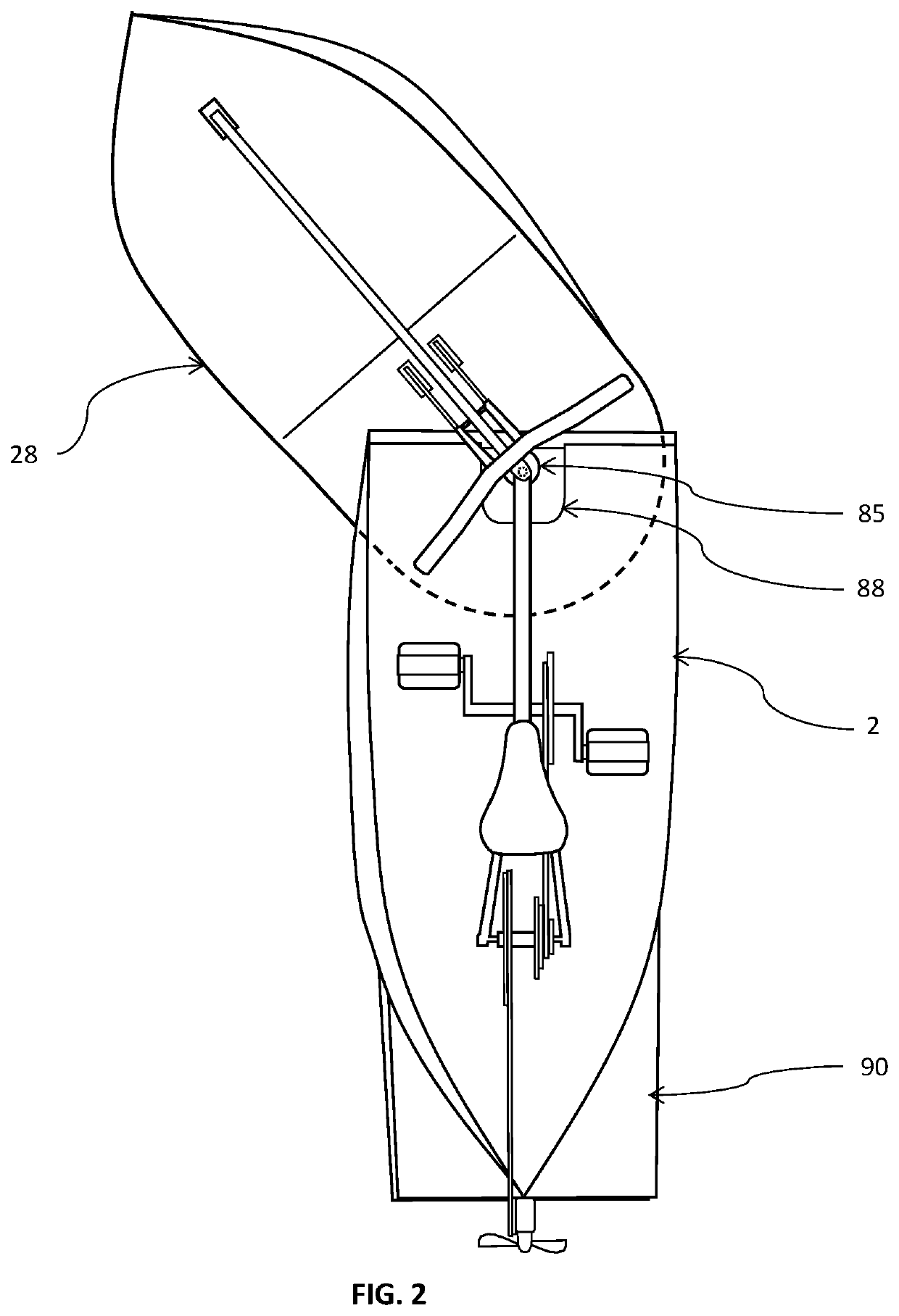
[0018]The fork assembly 6 is rigidly attached to adjustable brackets 26 on a fore flotation element 28 which is located forward of the main flotation element 2. The fore flotation element 28 is constructed of plastic, or plastic and fiber composite materials, with optional metal reinforcement. The lower end of a support 32 is adjustably attached to a surface bracket 34 mounted on the top deck of the fore flotation ...


PUM

PropertyMeasurementUnit
angleaaaaaaaaaa
gravityaaaaaaaaaa
hydraulic resistanceaaaaaaaaaa

Abstract

A unique watercraft that includes a plurality of flotation elements which are aligned longitudinally and fit together end to end, comprising the watercraft hull. Unlike other watercraft, it does not rely upon a low center of gravity for stability. A front flotation element pivots about an axis and this pivotal motion is used for both steering and for maintaining balance. The effective profile of the hull changes dynamically as the front flotation element is turned. These hull changes allow the operator to balance and make agile maneuvers. Equilibrium can be easily maintained in this manner when the watercraft is moving forward and when it is otherwise stationary in water. In a preferred embodiment, the watercraft is ridden like a bicycle. Balance is actively maintained by a rider who steers right and left to adjust transverse weight distribution. The riding experience feels similar to operating a conventional bicycle on land.

Description

CROSS REFERENCE TO RELATED APPLICATIONS[0001]This application claims the benefit of U.S. provisional patent application No. 62 / 796,486; submitted Jan. 24, 2019; entitled, Watercraft with Collinear Flotation ComponentsBACKGROUND OF THE INVENTION[0002]The embodiments and aspects described herein are regarding a watercraft. Conventional watercraft rely on a low center of gravity, with a wide base relative to the height of the load, to avoid capsizing. However, a wide watercraft hull increases water resistance resulting in slower speeds and hampered maneuverability. On small watercraft with narrow hulls, occupants must remain positioned close to the waterline to avoid causing unstable equilibrium, which is restrictive for the occupants. Various watercraft with multiple spaced floats and front or rear steering have been proposed, but these are slow to change course, and water flow is impeded by the configuration of floats and steering elements, resulting in lowered top speeds. Other atte...

Claims


Application Information

Patent Timeline
Patent Type & Authority Applications(United States)
IPC IPC(8): B63B34/50B63B1/14B63H16/20B63B5/24
CPCB63B34/50B63B1/14B63H2016/207B63B5/24B63B2005/242B63H16/20B63H2025/063
Inventor BROWN, DENNIS BROWN LEEBROWN, SEAN CLINTON RICHARD
Owner BROWN DENNIS BROWN LEE
Why Eureka
Try Eureka