Pulse hydraulic fracturing tool and method for coiled tubing dragging with bottom packer

Active Publication Date: 2021-07-22
CHONGQING INST OF GEOLOGY & MINERAL RESOURCES
View PDF0 Cites 0 Cited by
  • Summary
  • Abstract
  • Description
  • Claims
  • Application Information

AI Technical Summary

Benefits of technology

The present invention provides a pulse hydraulic fracturing tool and method that can more efficiently stimulate reservoirs. The tool has advantages of simple structure, good stability, and strong adaptability in the well. The parameters of pulse hydraulic energy, such as frequency and injection pressure, can be controlled to achieve precise stimulation. The nozzle has a long service life and the sealing way of the tool is simple and easy to access. The method associated with the tool solves the problem of easy nozzle damage and reduces the time and cost of hydraulic fracturing.

Problems solved by technology

However, conventional hydraulic fracturing technology also faces problems such as large scale and large energy consumption.
But as the limited service life and energy form of underground hydraulic injection tools, multiple string removal is often required for multi-section reservoir reformation.
It is more likely to crack rocks, forming a complex fracture network.
It has been widely recognized in the industry, but its development is limited by the level of equipment technology.
At present, there are few tools for underground pulse hydraulic energy generation in the market.
Existing tools cannot meet the needs of hydraulic fracturing with large displacement and large liquid volume, and there are problems such as complicated tool structure, poor adaptability of underground operation environment, short service life, and easy damage of nozzle after sand addition.
A single operation needs to run string more times. It increases time and cost.
The method associated with the tool solves the problems that the nozzle of the conventional pulse hydraulic fracturing tool is easy to be damaged by sand, and the method reduces the times of rising and lowering the pipe.

Method used


Image

  • Pulse hydraulic fracturing tool and method for coiled tubing dragging with bottom packer
  • Pulse hydraulic fracturing tool and method for coiled tubing dragging with bottom packer
  • Pulse hydraulic fracturing tool and method for coiled tubing dragging with bottom packer

Examples


Embodiment Construction

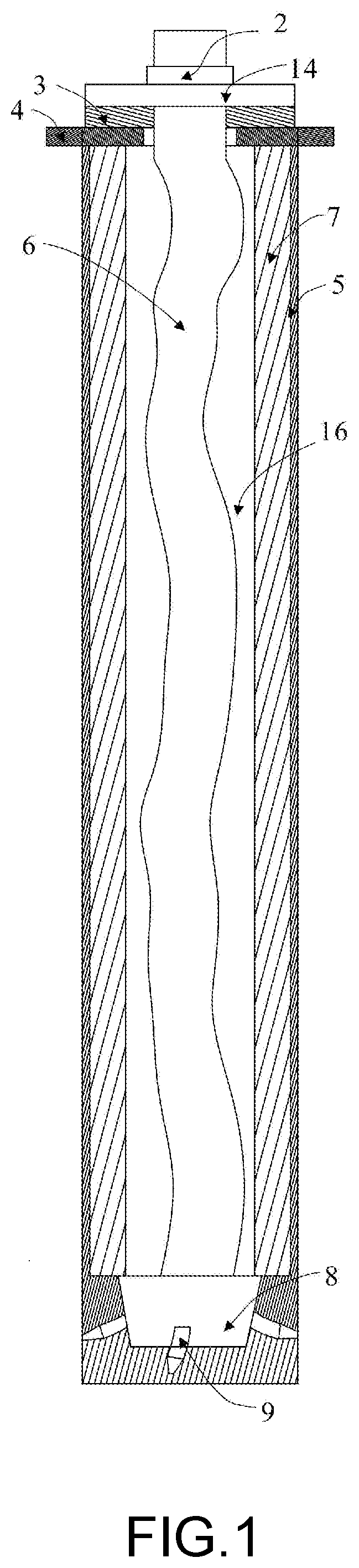
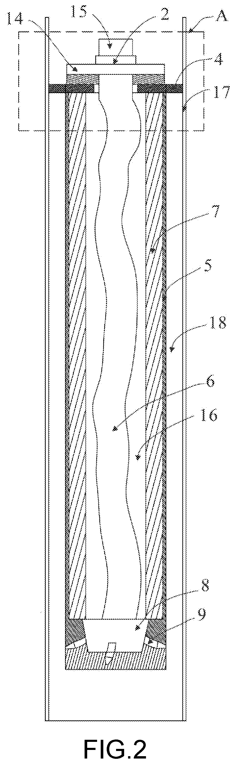
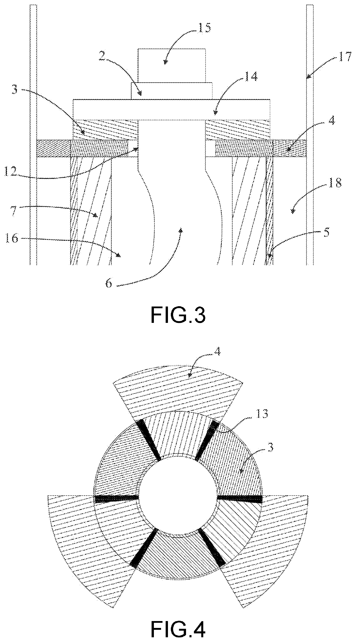
[0034]Referring to FIG. 1 to FIG. 8 a preferred embodiment of the invention is shown in detail. The invention provides a pulse hydraulic fracturing tool and method for coiled tubing dragging with bottom packer. The pulse hydraulic fracturing tool includes a pulse frequency regulator and liquid jetting device connected to each other. The pulse frequency regulating device has a rotor 6, a rotating member 3, a fixed member 4 and a stator 7. The rotor 6 has an internal channel 11 which a part of the first fluid in a coiled tubing 15 pass therethrough. The rotating member 3 and fixed member 4 are mounted on the rotor 6. The rotating member 3 rotates with the rotor 6. There are an eccentric setting and a gap 16 between the stator 7 and the rotor 6. The rotor 6 is driven by the first fluid. The liquid jetting device has a jet cavity 8 communicating the channel 11 inside the rotor 6 and the gap 16, and a nozzle 9 communicating the jet cavity 8. The part of the first fluid which the coiled t...


PUM


Abstract

A pulse hydraulic fracturing tool of coiled tubing dragging with bottom packer includes a pulse frequency regulating device and liquid jetting device connected to each other. The pulse frequency regulating device has a rotor, a rotating member, a fixed member and a stator. An eccentric setting is arranged between the stator and the rotor. A part of a first fluid provided by the coiled tubing flows into the jet cavity through the channel in the rotor, and drives the rotor to rotate with another part of the first fluid, such that a first passing region is formed between the rotating member and the fixed member in a predetermined pulse frequency. The another part of the first fluid flows into the jet cavity through the first passing region. The nozzle ejects two parts of the first fluid mixed in the jet cavity out.

Description

BACKGROUNDTechnical Field[0001]The present invention relates, in general, to hydraulic fracturing of oil and gas. It is a pulse hydraulic fracturing tool and method of coiled tubing dragging with bottom packer.Description of Related Art[0002]With the development and utilization of unconventional gas resources and marginal oil and gas reservoirs, the requirements for equipment and technology are constantly rising. Especially in order to achieve commercial development of unconventional gas resources such as shale gas, hydraulic fracturing technology is one of the indispensable means. It uses fracturing vehicles pump high-pressure liquid into reservoir in casing in conventional hydraulic fracturing, which can achieve the purpose of reservoir reformation through repeated operations. However, conventional hydraulic fracturing technology also faces problems such as large scale and large energy consumption. Hydraulic jet fracturing (HJF) is one of the hydraulic fracturing. Hydraulic jettin...

Claims


Application Information

Patent Timeline
IPC IPC(8): E21B43/26E21B47/06
CPCE21B43/26E21B33/12E21B47/06E21B43/114
Inventor LU, ZHAOHUIHE, PEI
Owner CHONGQING INST OF GEOLOGY & MINERAL RESOURCES
Why Eureka
Try Eureka