

A rotor for a wind turbine with a pitch bearing unit
a technology of pitch bearing unit and rotor, which is applied in the direction of machines/engines, other domestic objects, mechanical apparatus, etc., can solve the problems of accelerating wear and fatigue failure of the bearing unit, prone to sliding of two bearing element parts relative to each other, and prone to open the interface between the bearing element parts
Pending Publication Date: 2021-07-29
VESTAS WIND SYST AS
View PDF1 Cites 0 Cited by
- Summary
- Abstract
- Description
- Claims
- Application Information
AI Technical Summary
Benefits of technology
The invention provides a rotor for a wind turbine with improved handling of extreme loads and reduced risk of sliding and premature fatigue failure of bearing units as compared to prior art rotors. The C-shaped bearing element is designed to form an inner ring of the bearing unit, while the T-shaped bearing element is designed to form an outer ring of the bearing unit, which ensures that the rolling elements are subjected to forces acting on the centre of the roller in the lengthwise direction of the roller. This results in a more evenly distributed, and hence lower, contact pressure between the rolling element and the raceway pairs resulting in increased fatigue and extreme load capacity of the bearing unit. The first and second bearing element parts of the C-shaped bearing element can be easily assembled by bolts. The wind turbine blade can be easily and reliably attached to the bearing unit by means of bolts.
Problems solved by technology
When the bearing unit is subjected to high overturning moments from the wind turbine blade, the two bearing element parts are prone to slide relative to each other in the interface defined there between.
If the two bearing element parts slide relative to each other in this manner, subsequent loading combined with pitching of the bearing unit may accelerate wear and fatigue failure of the bearing unit.
Furthermore, a high overturning moment on the bearing unit may cause the interface between the bearing element parts to open.
When this occurs, blade bolts which clamp the two bearing element parts together will be highly stressed, and this may result in bolt fracture or loss of bolt pretension, which may in turn lead to premature failure of the bolts or sliding in the interface between the bearing element parts.
Method used
View moreImage
Smart ImageViewing Examples

Examples
first embodiment
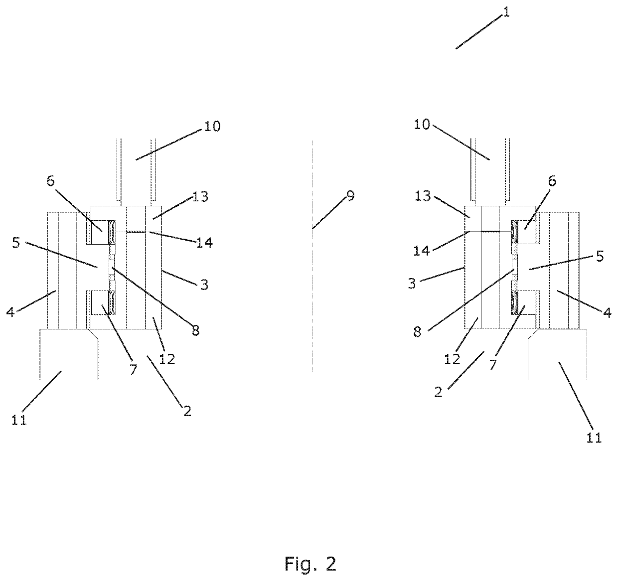
[0050]FIG. 2 is a cross sectional view of a rotor according to the invention,
second embodiment
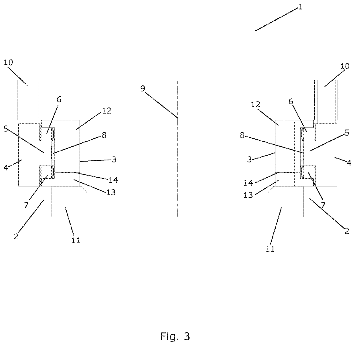
[0051]FIG. 3 is a cross sectional view of a rotor according to the invention,
[0052]FIG. 4 is a perspective view of part of a bearing unit for the rotor of FIG. 2,
[0053]FIG. 5 is a perspective view of part of a bearing unit for the rotor of FIG. 3,
[0054]FIG. 6 illustrates extreme loads acting on a bearing unit for a prior art rotor, and
[0055]FIG. 7 illustrates extreme loads acting on a bearing unit for a rotor according to an embodiment of the invention.
Login to View More PUM
 Abstract
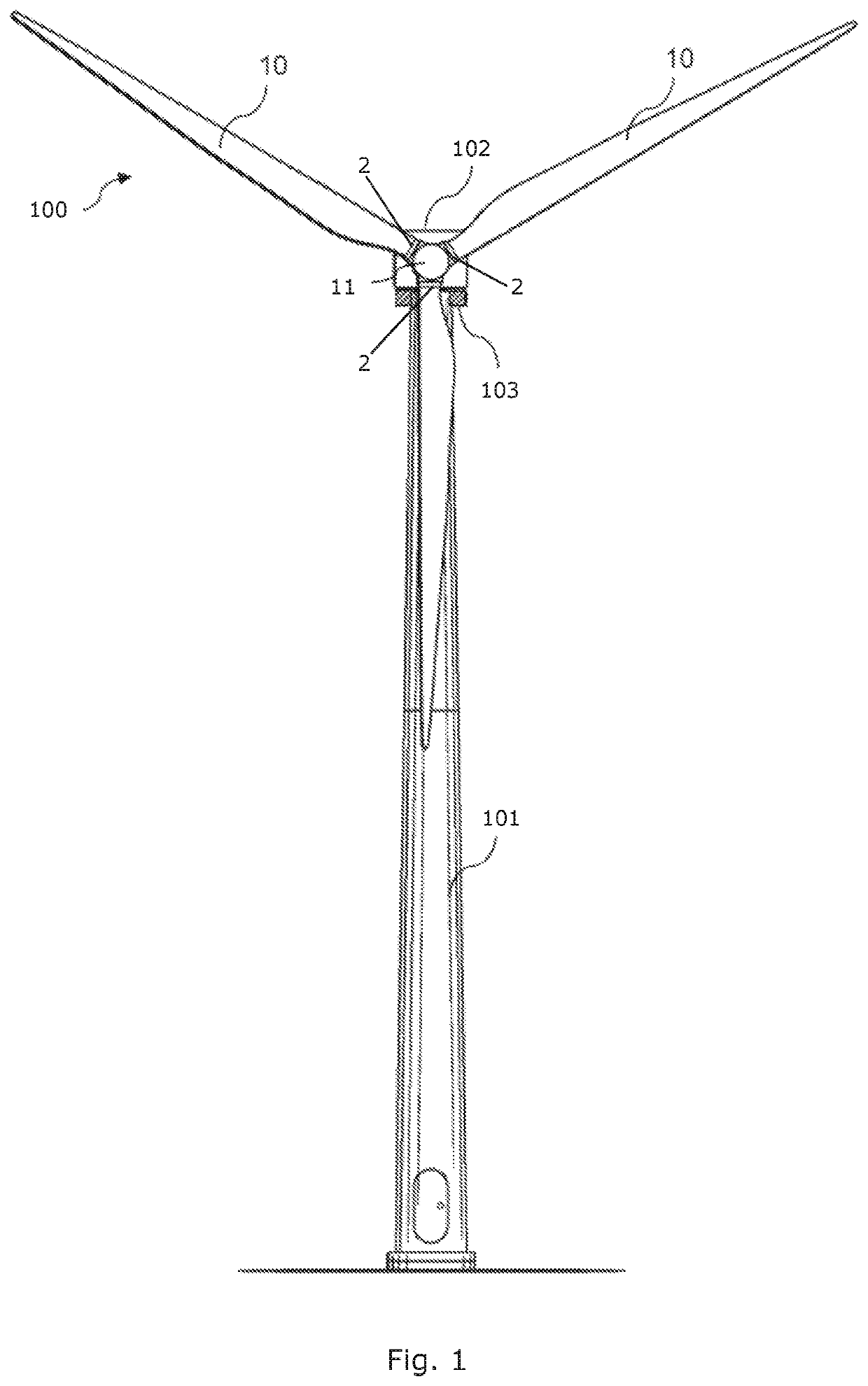
A rotor (1) for a wind turbine is disclosed. The rotor (1) comprises a hub (11) and at least one wind turbine blade (10), each wind turbine blade (10) being mounted on the hub (11) via a bearing unit (2). Each bearing unit (2) comprises a C-shaped bearing element (3) forming an inner ring and a T-shaped bearing element (4) forming an outer ring. The C-shaped bearing element (3) comprises a first bearing element part (12) and a second bearing element part (13). An interface (14) between the first bearing element part (12) and the second bearing element part (13) is positioned in such a manner that a third raceway pair (8) is formed between a protruding portion (5) of the T-shaped bearing element (4) and the first bearing element part (12) of the C-shaped bearing element (3) and the hub (11) or the wind turbine blade (10) is attached to the second bearing element part (13) of the C-shaped bearing element (3).
Description
FIELD OF THE INVENTION[0001]The present invention relates to a rotor for a wind turbine, the rotor comprising a hub and at least one wind turbine blade being mounted on the hub via a bearing unit. The rotor of the invention is very suitable for handling extreme loads on the bearing units of the wind turbine blades. The present invention further relates to a wind turbine comprising such a rotor.BACKGROUND OF THE INVENTION[0002]Wind turbines normally comprise a tower having a nacelle mounted thereon, and with a rotor mounted rotatably on the nacelle. A number of wind turbine blades are mounted on the rotor for catching the incoming wind and causing the rotor to rotate relative to the nacelle. The wind turbine blades may be mounted on the rotor via bearing units in order to allow them to perform pitch movements, i.e. in order to allow the wind turbine blades to change the angle of attack between the incoming wind and the wind turbine blades.[0003]The bearing units interconnecting the w...
Claims
Login to View More Application Information
Patent Timeline
 IPC IPC(8): F03D1/06B29D99/00B29L31/08F03D80/70
CPCF03D1/0675F03D1/0658F03D80/70B29D99/0028B29L2031/085F05B2260/79F16C19/381F16C33/60F16C43/04F16C2360/31Y02E10/72
InventorANDERSEN, LASSE KØGSSCHANDEL, PETER BÆKHØJTEIDELT, ANNA ELENAKABUS, SIMON
OwnerVESTAS WIND SYST AS