
Patch panel with lifting cassette removal

Active Publication Date: 2021-07-29
AFL IG LLC
View PDF0 Cites 0 Cited by
  • Summary
  • Abstract
  • Description
  • Claims
  • Application Information

AI Technical Summary

Benefits of technology

The patent describes a new invention and its benefits. The "technical effect" of the invention may be explained in part by the details provided in the description or through practice of the invention.

Problems solved by technology

Many enclosures in the market only allow either front side or rear side installation / maintenance; and, while there are a few solutions in the market that do allow for front and rear side access, the removal of the cassette module can be cumbersome in tight quarters.

Method used


Image

  • Patch panel with lifting cassette removal
  • Patch panel with lifting cassette removal
  • Patch panel with lifting cassette removal

Examples


Embodiment Construction

[0018]Reference now will be made in detail to embodiments of the invention, one or more examples of which are illustrated in the drawings. Each example is provided by way of explanation of the invention, not limitation of the invention. In fact, it will be apparent to those skilled in the art that various modifications and variations can be made in the present invention without departing from the scope or spirit of the invention. For instance, features illustrated or described as part of one embodiment can be used with another embodiment to yield a still further embodiment. Thus, it is intended that the present invention covers such modifications and variations as come within the scope of the appended claims and their equivalents.

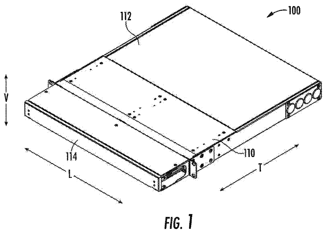
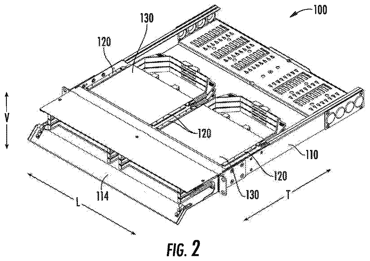
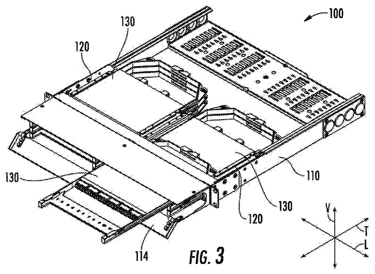
[0019]FIGS. 1 through 3 are perspective views of a patch panel 100 according to an example embodiment of the present subject matter. As may be seen in FIG. 1, patch panel 100 includes a cabinet or enclosure 110. Enclosure 110 may include a top panel 112 and...


PUM


Abstract

A patch panel includes a cabinet and a cassette. A pair of cassette guides is positioned within the cabinet. The pair of cassette guides are spaced along a lateral direction such that the cassette is receivable between the pair of cassette guides. The cassette is slidable along a transverse direction on the pair of cassette guides. At least one of the pair of cassette guides includes a first rail and a second rail that are spaced apart along a vertical direction. The cassette is slidable along the transverse direction between the first and second rails. Each end of the first rail is cantilevered such that each end of the first rail is moveable along the vertical direction.

Description

FIELD OF THE INVENTION[0001]The present subject matter relates generally to fiber optic patch panels or enclosures for pre-terminated cassette modules.BACKGROUND OF THE INVENTION[0002]Large data centers frequently deploy rows of racks and / or cabinets for cross-connect applications. The installation of high density fiber optic patch panels has been simplified and made more reliable by utilizing pre-terminated cassette modules installed in rack-mount enclosures. Although these pre-terminated cassettes have addressed many installation issues in terms of eliminating the need for field termination and polishing, they've introduced others. In particular, there are certain applications that require installation / maintenance from the rear side of the enclosure and others that lend to front-side installation / maintenance. Many enclosures in the market only allow either front side or rear side installation / maintenance; and, while there are a few solutions in the market that do allow for front a...

Claims


Application Information

Patent Timeline
IPC IPC(8): G02B6/44
CPCG02B6/4455G02B6/4452H04Q1/13H04Q1/023G02B6/44528G02B6/44526
Inventor YE, ZIDI
Owner AFL IG LLC
Features
  • Generate Ideas
  • Intellectual Property
  • Life Sciences
  • Materials
  • Tech Scout
  • Unparalleled Data Quality
  • Higher Quality Content
  • 60% Fewer Hallucinations
Learn More