
Method and sterilization system for improving duty cycle of robotic system and ultraviolet (UV) emitters disinfecting closed environment

Pending Publication Date: 2021-08-12
STERILIZ
View PDF0 Cites 0 Cited by
  • Summary
  • Abstract
  • Description
  • Claims
  • Application Information

AI Technical Summary

Benefits of technology

The present invention is a mobile system that automatically delivers UV-C light to all surfaces within a treatment space, including hard-to-clean, high-touch surfaces such as keyboards, computers, and bed rails, resulting in a cleaner, safer environment. Compared to other systems and techniques, the present invention provides faster processing-time and critical data capture that clearly demonstrates treated areas have received the necessary dosage of UV-C light needed to eradicate dangerous pathogens effectively. Another advantage of UV-C disinfection is that it leaves no harmful residue or vapors. The room is immediately available for occupancy. The battery of robotic system may be continuously get charged or recharged from connected UV emitter modules, which ensures uninterrupted operation of robotic system and UV emitter modules for disinfecting closed environment using UV emitter modules. Additionally, this saves cost and manhours for users.

Problems solved by technology

Even with such extreme statistics, many industry experts consider the problem to be severely underestimated.
Currently, Clostridium difficile (C. diff) is one of the most problematic pathogens in the healthcare industry.
It causes C. diff Infection (CDI) that sickens and kills humans.
Current cleaning methods such as a chemical disinfection are not working as a stand-alone practice.
UV light is known to destroy pathogens in water supplies and HVAC systems.
It is well-known that the UV portion of the light spectrum has the ability to inactivate the DNA of pathogens, making them unable to multiply.
Both of these types of equipment are unable to definitively deliver a specific dosage to a surface or volume of air because no measurement is taken at the location of interest.
This problem results in surfaces and air being over- or under-treated.
In the case of over-treating, excess treatment time slows down the facility's operations, thus adding to operating costs and reducing throughput, and results in excess exposure to room surfaces, which causes faster breakdown of the materials from which the surfaces are made.
In the case of under-treating, disinfection or sterilization is not assured, resulting in reduced efficacy and increased exposure to liability lawsuits.
Since it takes significant time to recharge the battery, the robotic UV disinfection equipment cannot be used for disinfecting desired area when it is being charged thus resulting in reduced duty cycle for the robotic UV disinfection equipment.

Method used


Image

  • Method and sterilization system for improving duty cycle of robotic system and ultraviolet (UV) emitters disinfecting closed environment
  • Method and sterilization system for improving duty cycle of robotic system and ultraviolet (UV) emitters disinfecting closed environment
  • Method and sterilization system for improving duty cycle of robotic system and ultraviolet (UV) emitters disinfecting closed environment

Examples


Embodiment Construction

[0032]The present invention will be understood more readily by reference to the following detailed description of the presently preferred embodiments.

[0033]Reference will now be made in detail to certain presently preferred embodiments of the invention, examples of which are illustrated in the accompanying drawings. Wherever possible, the same reference numerals are used throughout the drawings to refer to the same or like parts.

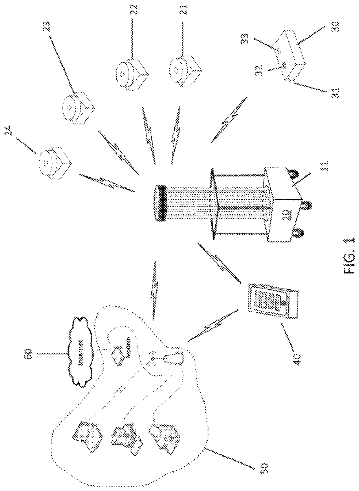
[0034]As broadly embodied in FIG. 1, a sterilization system includes an emitter 10, a sensing system consisting of UV sensors 21-24, door sensor 30, a remote control 40, an optional wireless local area network (WLAN) 50, and an optional Internet connection 60 for the optional WLAN.

[0035]In more detail with reference to FIG. 1, the emitter subsystem includes the emitter 10 which is a mobile structure on wheels with a plurality of lamps that emit ultraviolet light when energized by their corresponding electronic ballast(s). Other possible embodiments of an emi...


PUM


Abstract

Method, sterilization system and robotic system for improving duty cycle of Ultraviolet (UV) emitter modules disinfecting closed environment. Sterilization system includes robotic system and plurality of UV emitter modules. Robotic system receives signal corresponding to discharge of battery from one of plurality of UV emitter modules. Each of plurality of UV emitter modules includes UV light source for disinfecting closed environment. Robotic system detects location of UV emitter module amongst plurality of UV emitter modules and maneuvers to location of UV emitter module, mounts UV emitter module and maneuvers UV emitter module to charging dock for charging battery of UV emitter module. After charging, robotic system maneuvers UV emitter module to pre-defined area for disinfecting pre-defined area of closed environment. Robotic system includes battery charged through UV emitter module when UV emitter module is getting charged, or when UV emitter module mounted to robotic system includes battery that is fully charged.

Description

CROSS-REFERENCE TO RELATED APPLICATIONS[0001]This application claims priority to a U.S. Provisional Patent Application No. 63 / 029,292, filed May 22, 2020; which is a continuation-in-part of U.S. application Ser. No. 16 / 164,150, filed Oct. 18, 2018; which is a continuation-in-part of U.S. application Ser. No. 15 / 169,164, filed May 31, 2016 (now U.S. Pat. No. 10,226,541); which is a continuation of U.S. application Ser. No. 14 / 263,774, filed Apr. 28, 2014 (now U.S. Pat. No. 10,010,633); which is a continuation-in-part of U.S. application Ser. No. 13 / 964,874, filed Aug. 12, 2013 (now U.S. Pat. No. 9,345,798); which is a CIP of Ser. No. 13 / 446,563, filed Apr. 13, 2012 (now abandoned); which claims priority to U.S. Provisional Patent Application No. 61 / 475,722, filed Apr. 15, 2011; and U.S. application Ser. No. 15 / 169,164 is a divisional of U.S. application Ser. No. 13 / 964,874, filed Aug. 12, 2013 (now U.S. Pat. No. 9,345,798); all of which are hereby incorporated by reference in their e...

Claims


Application Information

Patent Timeline
IPC IPC(8): A61L2/10A61L9/015A61L2/20A61L9/20A61L2/24G01J1/02G01J1/42
CPCA61L2/10A61L9/015A61L2/208A61L9/20A61L2/24A61L2202/16G01J2001/0276A61L2202/25G01J1/429A61L2202/11A61L2202/14A61L2/202G01J1/0219G01J1/0247
Inventor TRAPANI, SAMUEL RICHARD
Owner STERILIZ
Learn More