Rowing machine

a technology of rowing machine and handle, which is applied in the field of rowing exercise machines, can solve the problems of inability to accurately calculate the the resistance device cannot provide a uniform resistance force to the user, and the diameter of the handle gradually decreases, so as to achieve uniform resistance force, simple structure, and accurate calculation of the travel distance of the handle pulled

Inactive Publication Date: 2021-08-12
GEARON MICHAEL JAMES
View PDF0 Cites 11 Cited by
  • Summary
  • Abstract
  • Description
  • Claims
  • Application Information

AI Technical Summary

Benefits of technology

[0005]The present invention has been accomplished in view of the above-noted circumstances. It is an objective of the present invention to provide a rowing machine, which can provide...

Problems solved by technology

One of the drawbacks of the above-mentioned conventional rowing machine lies in that the resistance device cannot provide a uniform resistance force to the user during the drive phase of the rowing stroke due to the grounds that the winding body, which is formed by the long blet that is wrapped around the shaft for several windings, will gradually decrease in its diameter during...

Method used


Image

  • Rowing machine
  • Rowing machine
  • Rowing machine

Examples


Embodiment Construction

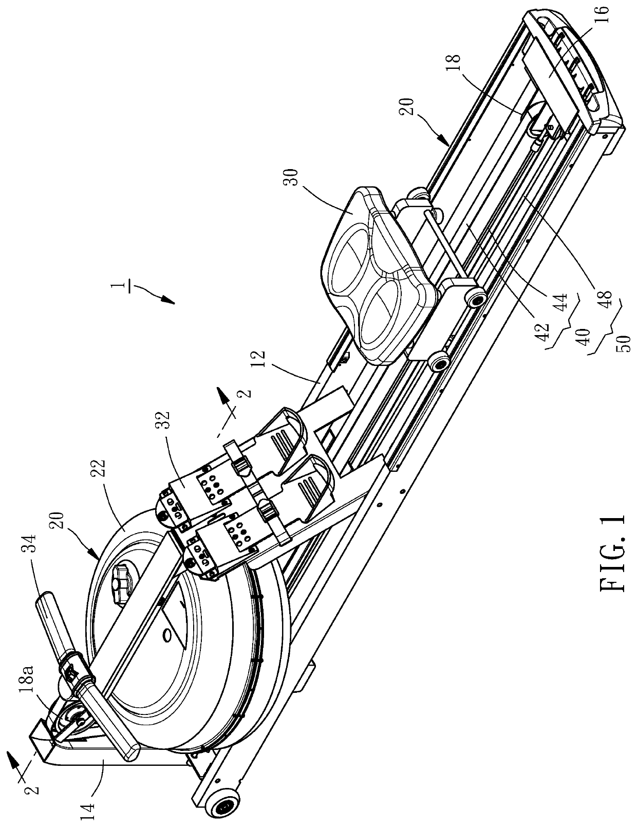
[0015]Hereunder four embodiments are given for illustrating the structural features and effects of the present invention. As shown in FIG. 1, a rowing machine 1 provided by a first embodiment of the present invention is composed of a base mount 10, a resistance device 20, a seat 30, a foot pedal rack 32, a handle 34, a transmission member 40 and a resilient member 48.

[0016]The base mount 10 comprises two guide rails 12 extending in a longitudinal direction, a front fastening rack 14 disposed on the front ends of the two guide rails 12, a rear fastening rack 16 disposed on the rear ends of the two guide rails 12, and a plurality of pulleys 18 mounted to the front fastening rack 14 and the rear fastening rack 16, respectively.

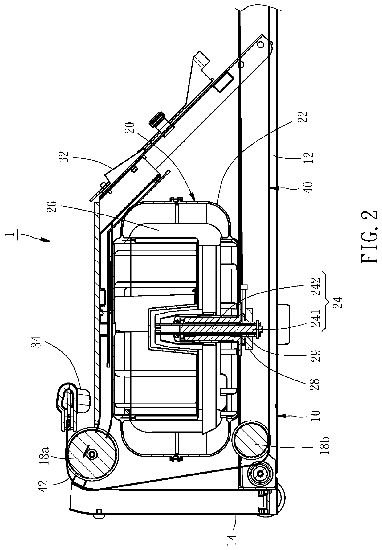
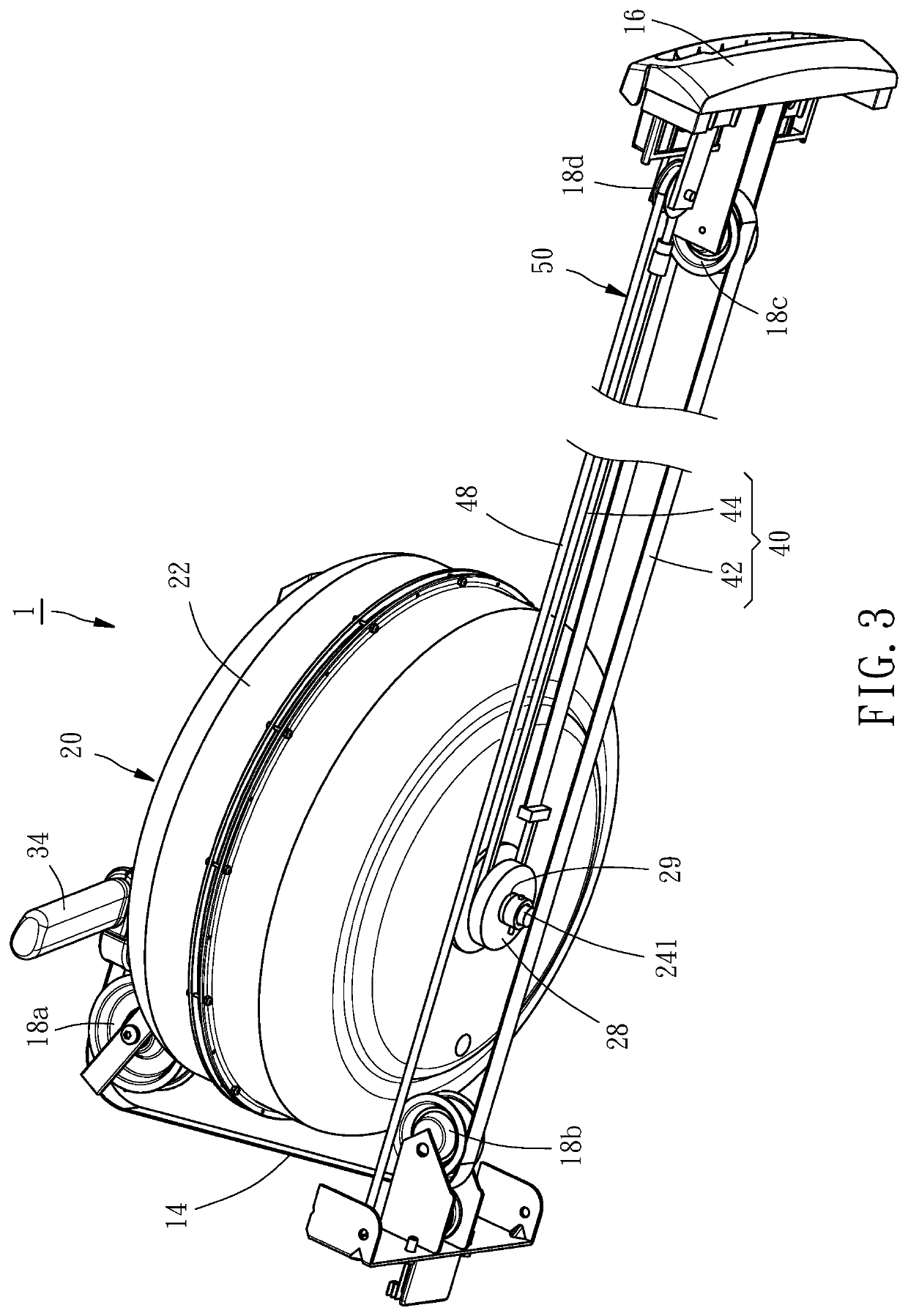
[0017]As shown in FIG. 2, the resistance device 20 comprises a housing 22, a shaft 24 extending from an outside of the housing 22 into an inside of the housing 22, a plurality of blades 26, and a transmission wheel 28. The housing 22 is shaped like a flat cylindr...


PUM


Abstract

A rowing machine includes a base mount with pulleys, a resistance device, a handle, a transmission member, and a resilient member. The resistance device includes a housing, a shaft having an outer shaft section located outside the housing, and an inner shaft section located inside the housing, a plurality of blades mounted to the inner shaft section, and a transmission wheel mounted to the outer shaft section. The transmission member extends from the handle and has an engagement section engaged with the transmission wheel. The resilient member has a first end disposed to the based mount, and a second end connected with the transmission member in a way that the transmission member and the resilient member wrap around the pulleys. As such, the rowing machine can provide uniform resistance and accurately determine the travel distance of the handle that is pulled by a user.

Description

BACKGROUND OF THE INVENTION1. Field of the Invention[0001]The present invention relates generally to exercise apparatus, and more particularly, to a rowing exercise machine.2. Description of the Related Art[0002]The conventional rowing machines employ a handle connected with a long belt wrapping around the shaft of a resistance device for several circumferential windings. When a user pulls the handle backward, the long belt drives the shaft to rotate, thereby providing a desired resistance force against the user. In the recovery phase of the rowing stroke, i.e., in the process that the handle returns to its initial position, the long belt will be rewrapped around the shaft again under an effect of a spring. By preforming the rowing stroke repeatedly, the effect of exercise and fitness can be achieved.[0003]One of the drawbacks of the above-mentioned conventional rowing machine lies in that the resistance device cannot provide a uniform resistance force to the user during the drive p...

Claims


Application Information

Patent Timeline
IPC IPC(8): A63B22/00A63B69/06
CPCA63B22/0076A63B2069/062A63B2022/0079A63B69/06A63B21/0084
Inventor GEARON, MICHAEL JAMES
Owner GEARON MICHAEL JAMES
Why Eureka
Try Eureka