
Integrated three dimensional display and method of recording identification information

a three-dimensional display and identification information technology, applied in the field of integrated three-dimensional displays, can solve the problems of not being suitable for mass production, requiring more cycle time for holograms using rgb three-color lasers, and high cost of photosensitive materials, so as to facilitate the recognition of two-dimensional information, increase the contrast of two-dimensional information, and increase the recognition rate per unit time

Active Publication Date: 2021-08-12
TOPPAN PRINTING CO LTD
View PDF0 Cites 0 Cited by
  • Summary
  • Abstract
  • Description
  • Claims
  • Application Information

AI Technical Summary

Benefits of technology

The patent proposes a method to partially shield the recording surface to record two-dimensional information on holograms. This method prevents the commoditization of holograms and provides a unique identifier for each hologram.

Problems solved by technology

However, the technique disclosed in PTL 1 does not consider the parallax in the vertical direction, and is effective only when the parallax is in the horizontal direction.
In addition, color shift occurs in the vertical direction, which causes iridescence.
This iridescent shift is a typical effect that occurs to most holograms currently commonly used, and leads to commoditization.
However, the photosensitive materials are expensive compared with embossing holograms that use a general UV-curable resin.
Further, Lippmann holograms using an RGB three-color laser require more cycle time than embossing holograms, and are not suitable for mass production.

Method used


Image

  • Integrated three dimensional display and method of recording identification information
  • Integrated three dimensional display and method of recording identification information
  • Integrated three dimensional display and method of recording identification information

Examples


Embodiment Construction

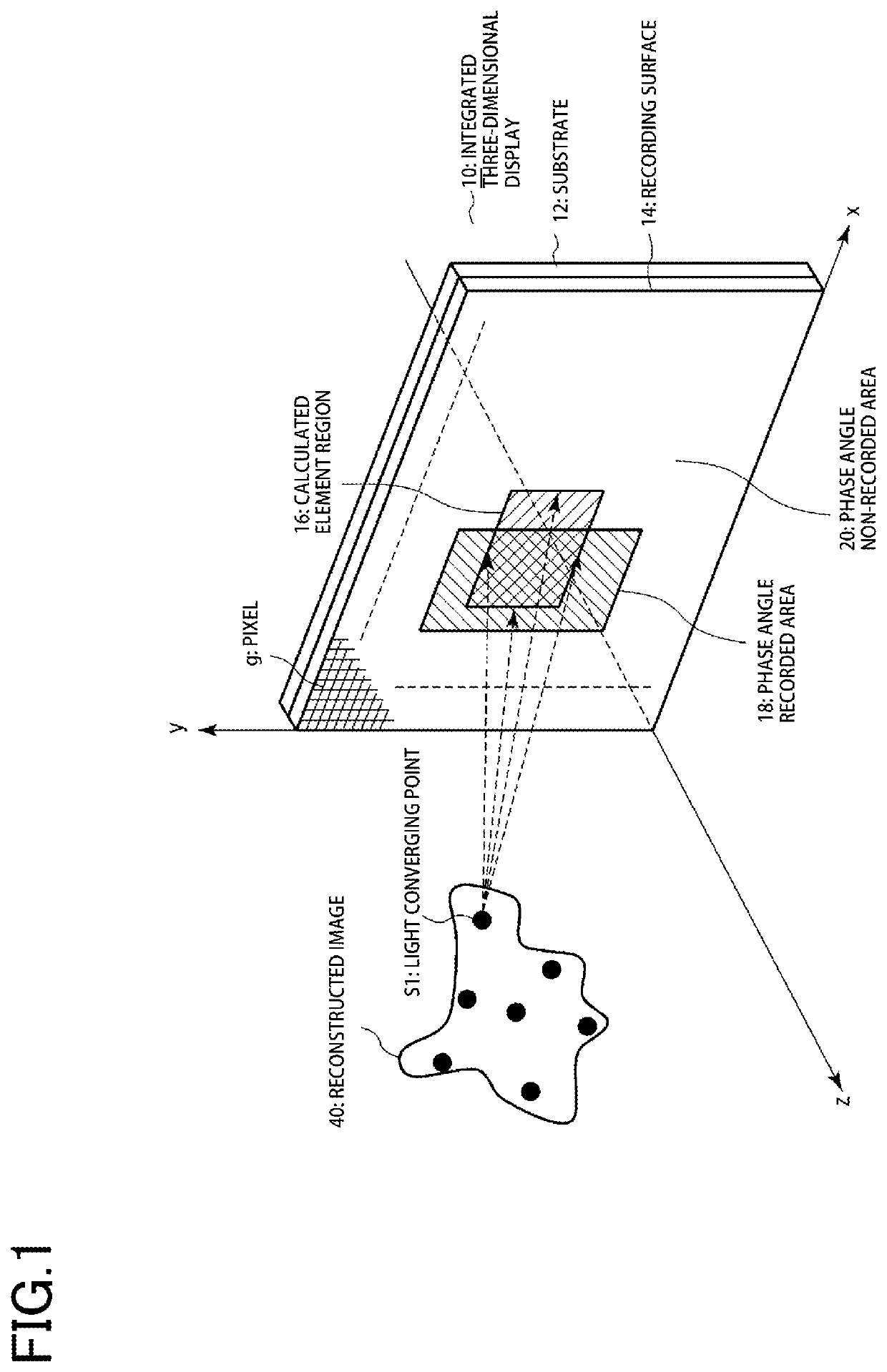
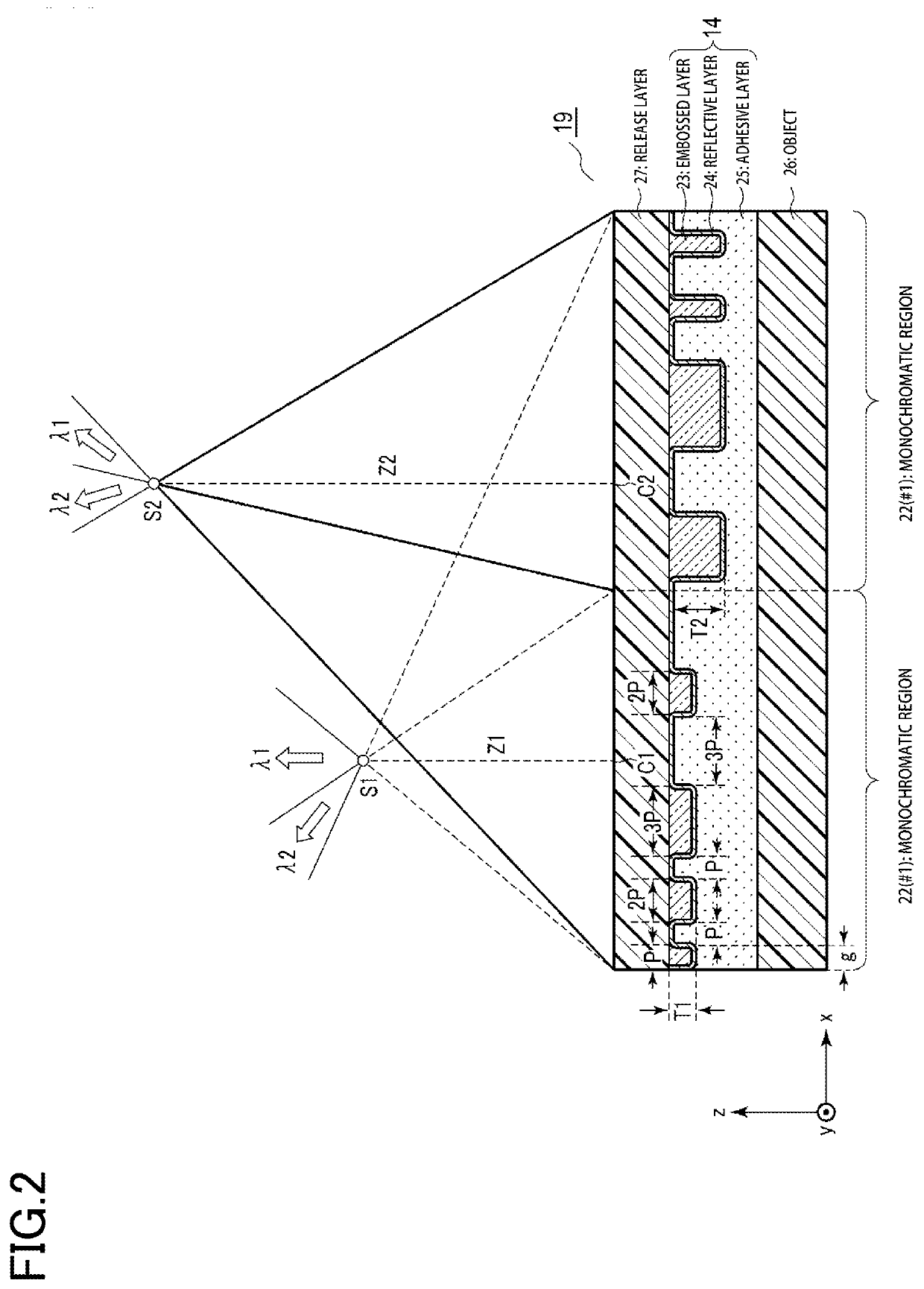
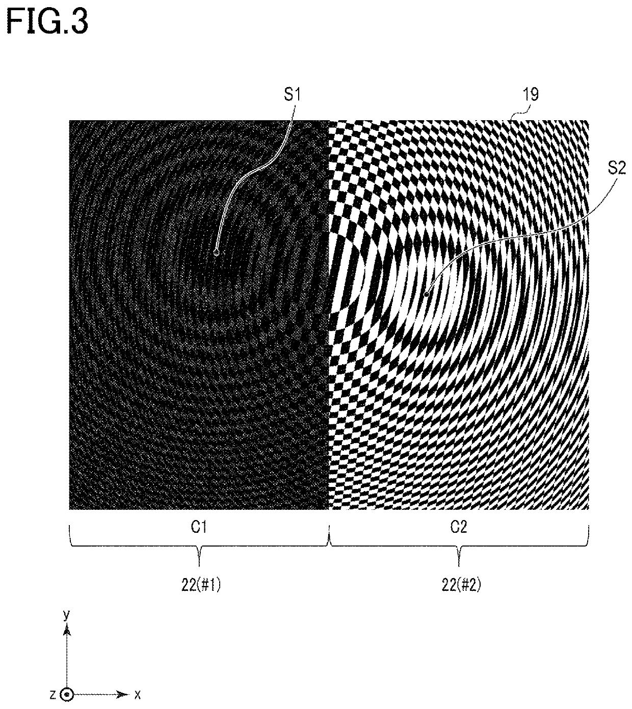
[0092]Embodiments of the present invention of will be described below with reference to the drawings. In the following description of the drawings to be referred, components or functions identical with or similar to each other are given the same or similar reference signs, unless there is a reason not to. It should be noted that the drawings are only schematically illustrated, and thus the relationship between thickness and two-dimensional size of the components, and the thickness ratio between the layers, are not to scale. Therefore, specific thicknesses and dimensions should be understood in view of the following description. As a matter of course, dimensional relationships or ratios may be different between the drawings.

[0093]Further, the embodiments described below are merely examples of configurations for embodying the technical idea of the present invention. The technical idea of the present invention does not limit the materials, shapes, structures, arrangements, and the like...


PUM


Abstract

An integrated three-dimensional display includes a recording surface which includes a calculated element region in which phase components of light from light converging points of a holographic reconstructed image are calculated, and a phase angle recorded area for recording a phase angle calculated based on the phase components. The phase angle recorded area includes a plurality of monochromatic regions having a uneven structure surface. The phase angle is recorded in an overlap area in which the calculated element region and the phase angle recorded area overlap each other. Light converges on the light converging points at specific distances from the recording surface, the specific distances being determined for the respective light converging points even when light reflected from the plurality of monochromatic regions converges.

Description

CROSS-REFERENCE TO RELATED PATENT APPLICATIONS[0001]This application is a continuation application filed under 35 U.S.C. § 111(a) claiming the benefit under 35 U.S.C. §§ 120 and 365(c) of International Patent Application No. PCT / JP2019 / 040513, filed on Oct. 15, 2019, which is based upon and claims the benefit of priority to Japanese Patent Application No. 2018-195365, filed on Oct. 16, 2018, the disclosures of which are incorporated herein by reference in their entireties.TECHNICAL FIELD[0002]Embodiments of the present invention relate to integrated three-dimensional displays in which, for example, phase components of spatial information calculated by a computer are recorded to apply to a hologram, and also relate to methods of recording identification information.BACKGROUND[0003]As disclosed in the following prior art documents, there have been recently disclosed computer-generated holograms controlled by interference of light calculated by a computer: (PTL 1) JP 4525151 B2; (PTL 2...

Claims


Application Information

Patent Timeline
Patent Type & Authority Applications(United States)
IPC IPC(8): H04N13/128H04N13/302G03H1/14G03H1/00
CPCH04N13/128H04N13/302G03H2001/0088G03H1/0005G03H1/14B42D25/328B42D25/373G03H1/0011G03H1/30G03H2001/303G03H1/0244G03H2250/10G03H2250/42G03H2210/53G03H2270/52G03H2224/04G03H2250/40G03H1/0808G03H2001/266G03H1/28G03H2001/2263G03H1/0841G03H1/268G09F19/125G11B7/0065G11B7/24094G11B7/24044G03H2210/12
Inventor KAGOTANI, AKIHITOUMEDA, KOZUEKODA, SOKO
Owner TOPPAN PRINTING CO LTD
Learn More