Co2 scrubber with moving bed structure

a scrubber and moving bed technology, applied in the direction of lighting and heating apparatus, heating types, separation processes, etc., can solve the problems of complex valving system operation, poor outside air quality, and significant energy consumption for heating, cooling and other problems

Pending Publication Date: 2021-08-19
CARRIER CORP
View PDF0 Cites 2 Cited by
  • Summary
  • Abstract
  • Description
  • Claims
  • Application Information

AI Technical Summary

Benefits of technology

[0018]In another embodiment, an air handling unit including a housing, a return air damper through which a return airflow is directed into the air handling unit, a supply air damper through which a supply airflow is directed from the air handling unit into a conditioned space, and one or more of a heating coil and a cooling coil located in the housing configured to alter a temperature of the return airflow in the housing. A carbon dioxide scrubber is operably connected to the air handling unit. The carbon dioxide scrubber includes an adsorption chamber through which an adsorption airflow is directed, a regeneration chamber through which a regeneration airflow is

Problems solved by technology

Consequently, a significant amount of energy is consumed for heating, cooling and/or dehumidification of the outside air before it is introduced into the conditioned space.
Further, in many locations, the outside air quality i

Method used


Image

  • Co2 scrubber with moving bed structure
  • Co2 scrubber with moving bed structure
  • Co2 scrubber with moving bed structure

Examples


Embodiment Construction

[0041]A detailed description of one or more embodiments of the disclosed apparatus and method are presented herein by way of exemplification and not limitation with reference to the figures.

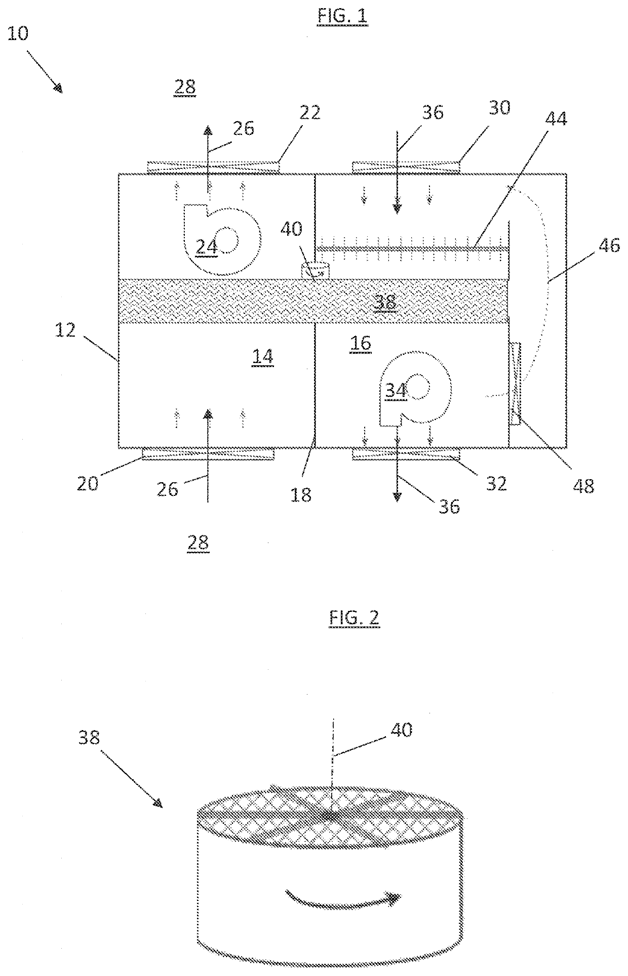
[0042]An embodiment of a carbon dioxide (CO2) scrubber 10 is shown in FIG. 1. The CO2 scrubber 10 includes a scrubber housing 12 having an adsorption chamber 14 and a regeneration chamber 16, separated by a divider wall 18. The adsorption chamber 14 includes an adsorption inlet damper 20 and an adsorption outlet damper 22. In some embodiments, an adsorption chamber fan 24 is located in the adsorption chamber 14 to urge an adsorption airflow 26 through the adsorption chamber 14. In some embodiments, the adsorption airflow 26 is an indoor airflow from a conditioned space 28 that is reintroduced to the conditioned space 28 after passing through the adsorption chamber 14.

[0043]Similarly, the regeneration chamber 16 includes a regeneration inlet damper 30 and a regeneration outlet damper 32. In some e...


PUM

PropertyMeasurementUnit
Flow rateaaaaaaaaaa
Energyaaaaaaaaaa
Adsorption entropyaaaaaaaaaa

Abstract

A carbon dioxide scrubber includes an adsorption chamber through which an adsorption airflow is directed, a regeneration chamber through which a regeneration airflow is directed, and a divider wall separating the adsorption chamber from the regeneration chamber. A carbon dioxide sorbent bed extends across the adsorption chamber and the regeneration chamber. The carbon dioxide sorbent bed is configured to adsorb carbon dioxide from the adsorption airflow into the sorbent bed and exhaust carbon dioxide from the carbon dioxide sorbent bed into the regeneration airflow. The carbon dioxide sorbent bed is continuously movable through the adsorption chamber and the regeneration chamber.

Description

BACKGROUND[0001]Exemplary embodiments pertain to the art of indoor air quality management, and in particular to mitigation of carbon dioxide (CO2) accumulation in a building or other structure.[0002]A certain amount of outside air (so called “fresh air”) is mandated to be supplied to an indoor conditioned space so as to dilute indoor generated gases caused by human occupancy, furniture offgassing or equipment operation (such as printers). Such gases typically include CO2, formaldehyde (HCHO), volatile organic compounds (VOCs), etc. Introduction of the outside air is used to maintain acceptable indoor air quality (IAQ) for ventilation code compliance. Consequently, a significant amount of energy is consumed for heating, cooling and / or dehumidification of the outside air before it is introduced into the conditioned space. Further, in many locations, the outside air quality is poor, and includes particulates, ozone, nitrogen and sulfur oxides (NOx, Sox), and other pollutants undesirabl...

Claims


Application Information

Patent Timeline
IPC IPC(8): B01D53/08F24F8/158
CPCB01D53/08F24F8/158B01D2253/102B01D2257/504B01D2259/40084B01D2258/06B01D2259/40088B01D2259/4508B01D2257/80B01D53/06B01D2259/4009B01D2253/108B01D2253/1124B01D2253/116B01D2253/204B01D2253/202B01D2253/25B01D2257/708B01D2257/704Y02C20/40
Inventor ZHONG, ZHIPENGTHIBAUD, CATHERINE
Owner CARRIER CORP
Why Eureka
Try Eureka