Apparatus and method for transporting magnetic particles

Pending Publication Date: 2021-08-19
HAHN SCHICKARD GESELLSCHAFT FUER ANGEWANDTE FORSCHUNG EV
View PDF0 Cites 0 Cited by
  • Summary
  • Abstract
  • Description
  • Claims
  • Application Information

AI Technical Summary

Benefits of technology

The invention is a device that can transport magnetic particles quickly and efficiently in fluidic structures within a substrate. It achieves this by using an oblique chamber wall that increases the magnetic force and reduces friction, allowing the particles to be transported more easily. The device also allows for continuous rotation, which controls the state of the liquid and prevents mixing of liquids within the structures. Additionally, the device can transport magnetic particles from a dry or semi-dry state to a wet state by first contacting a liquid in a separate chamber. This results in improved transport efficiency and control of the particles.

Problems solved by technology

Here, however, a magnetic force acting on particles during GTM cannot be adjusted in a quantifiable manner, since liquids are present in an uncontrolled state during standstill (regarding the formation of the interface between liquid and gas).
Further, the method is not universally applicable (i.e., for liquids of any wetting characteristics).
Consequently, undesired mixing of different liquids can result which can affect the quality of the analysis to be performed.
Additionally, the method uses only a fraction of the theoretically usable magnetic force, since the main component of the magnetic force vector (Fmag) in the described configuration acts orthogonally to the wall of the cartridge facing the permanent magnet (Fs) and not in the direction of transport of the particles (Fr), which is why a transport of the particles cannot be performed very efficiently with the method.
However, these described papers merely allow the control of particle movements within a microfluidic chamber and not the transport between different chambers.
In the above stated automation of laboratory processes in centrifugal microfluidic cartridges, the challenge of specifically manipulating the movement of the magnetic particles to implement the desired operations arises.
In centrifugal microfluidics, in particular the following problems are insufficiently solved:Currently, there is no method allowing quantitative prognosis on the forces acting on the particles at the time of transferring the particles out of a liquid.Existing methods allow either mixing or transferring or holding back particles but not all these unit operations simultaneously.Existing methods allow no control of the force acting on the magnetic particles based on the chamber geometry (passive, monolithic).Existing methods allow no controllable state of the liquids during the transfer of particles from one chamber into another chamber.Existing methods are not suitable for handling highly wetting liquids (such as alcohols, surfactants) which are, however, frequently used in the above stated fields of application.

Method used


Image

  • Apparatus and method for transporting magnetic particles
  • Apparatus and method for transporting magnetic particles
  • Apparatus and method for transporting magnetic particles

Examples


Embodiment Construction

re embodiments of the present invention will be discussed in more detail below, it should be noted that identical, functionally equal or equal elements, objects and / or structures are provided with the same or similar reference numbers in the different figures, such that the description of these elements illustrated in different embodiments is inter-exchangeable or inter-applicable.

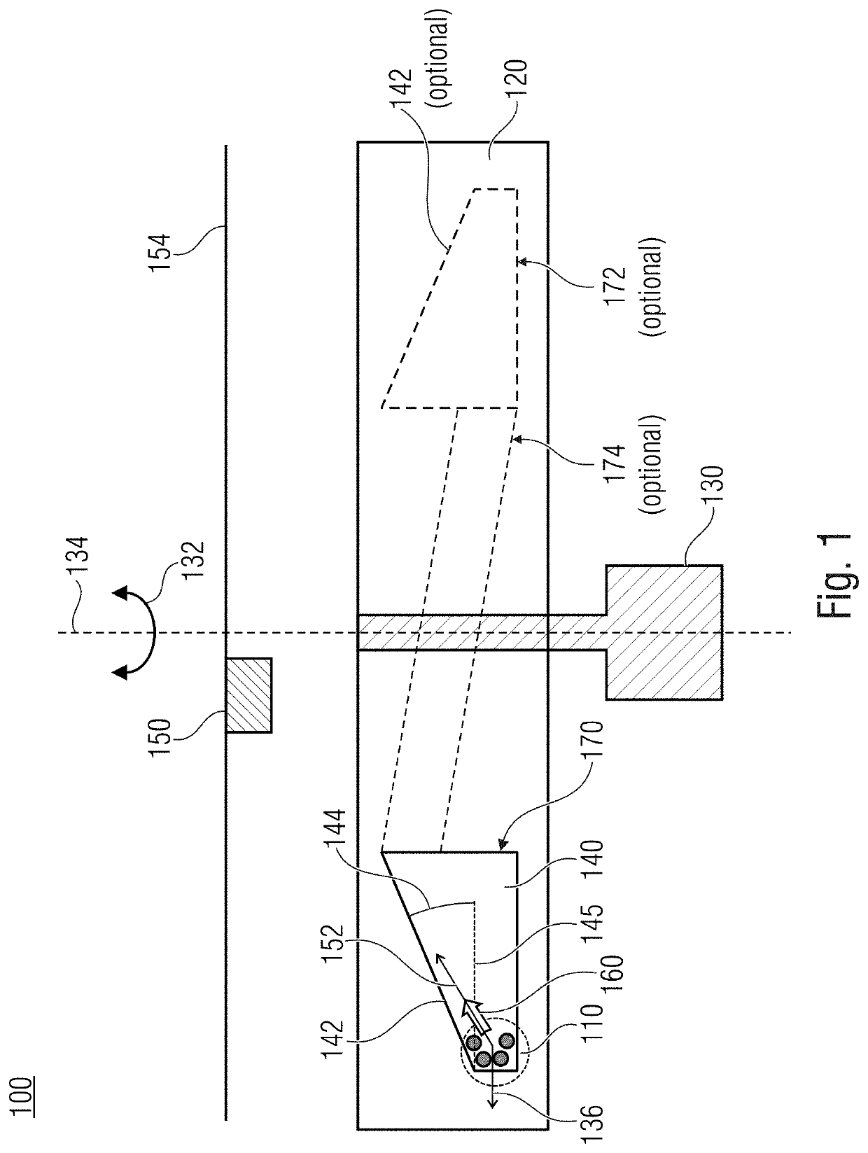
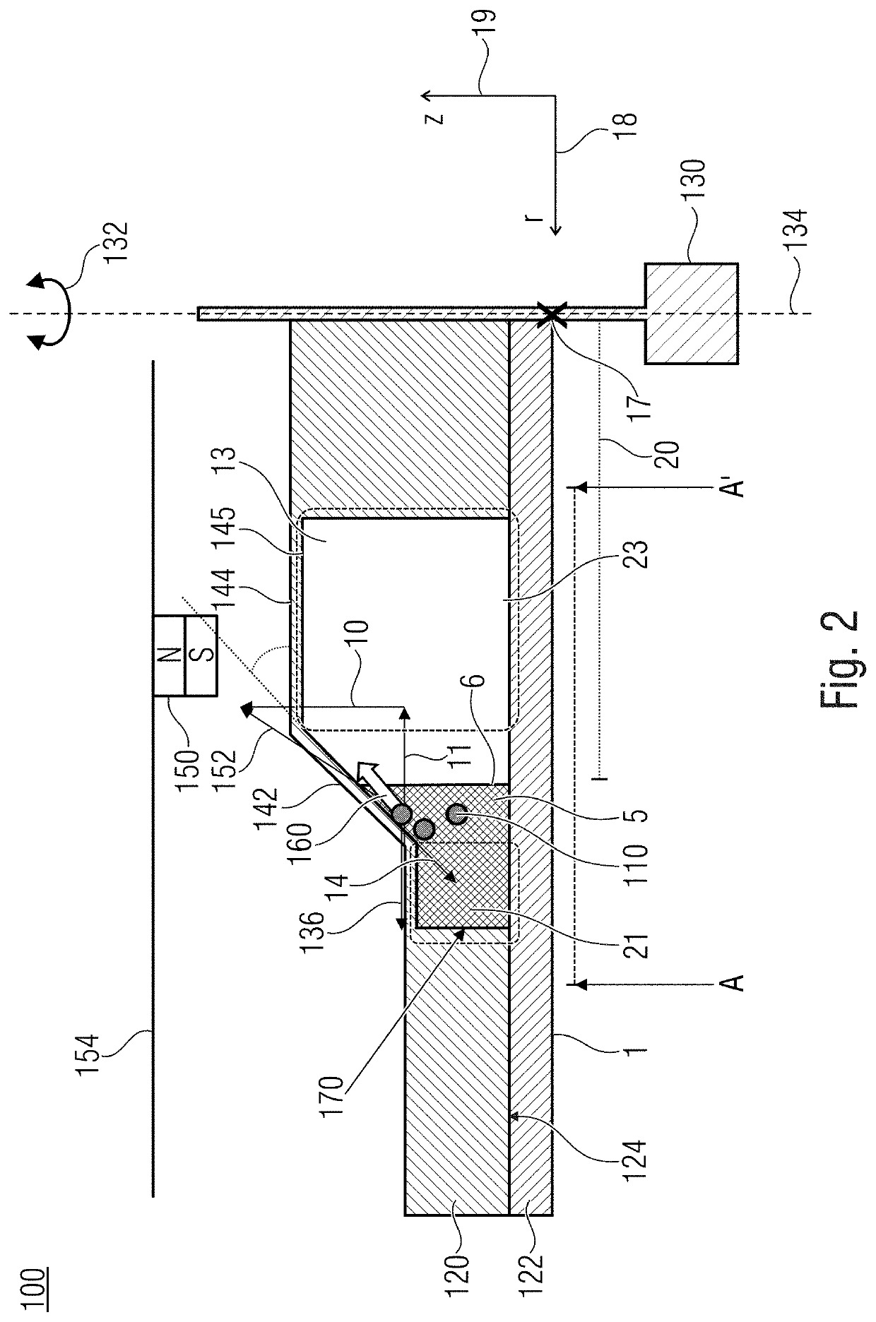
[0065]FIG. 1 shows a schematic illustration of an apparatus 100 for transporting magnetic particles 110. The schematic illustration of FIG. 1 can illustrate a cross-section through the apparatus 100. The apparatus 100 can comprise a substrate 120 that can be configured for a rotation 132 around an axis of rotation 134. Further, fluidic structures 140 can be arranged in the substrate 120, which can comprise an oblique chamber wall 142 that can be arranged at an angle α144 with respect to a plane 145 perpendicular to the axis of rotation 134. A magnetic force element 150 can be arranged radially inside the o...


PUM


Abstract

An apparatus for transporting magnetic particles. The apparatus can comprise a substrate that can be configured for rotating around an axis of rotation. Further, fluidic structures can be arranged in the substrate, which can comprise an oblique chamber wall that can be arranged at an angle α with respect to a plane perpendicular to the axis of rotation. A magnetic force element can be arranged radially inside the oblique chamber wall with respect to the axis of rotation and can be configured to apply a magnetic force to the magnetic particles disposed in the fluidic structures depending on a positional relationship between the magnetic force element and the fluidic structures, wherein the oblique chamber wall is inclined towards the magnetic force element.

Description

CROSS-REFERENCE TO RELATED APPLICATIONS[0001]This application is a continuation of copending International Application No. PCT / EP2019 / 080517, filed Nov. 7, 2019, which is incorporated herein by reference in its entirety, and additionally claims priority from German Application No. 10 2018 219 091.7, filed Nov. 8, 2018, which is also incorporated herein by reference in its entirety.[0002]Embodiments according to the invention relate to an apparatus and a method for transporting magnetic particles.BACKGROUND OF THE INVENTION[0003]In the following, three existing approaches of the field of centrifugal microfluidics will be presented, which allow automated manipulation of magnetic particles in a rotating system.[0004]Strohmeier et al. have patented [1] and published [2] a method called “gas-phase transition magnetophoresis” (GTM). In this method for transporting magnetic particles, a centrifugal microfluidic cartridge (called “lab disk”) is located below a stationary permanent magnet. H...

Claims


Application Information

Patent Timeline
IPC IPC(8): B01L3/00B03C1/28
CPCB01L3/502761B03C1/288B01L2200/0668B03C1/01B01L2400/043B03C2201/18B03C2201/26B01L2400/0409B01L2300/0803B01L2300/0864B01L2300/087G01N35/0098G01N35/00069B01L2300/0874B01L2400/086B03C1/0335B03C1/0332
Inventor HIN, SEBASTIANMITSAKAKIS, KONSTANTINOSROMBACH, MARKUSPAUST, NILS
Owner HAHN SCHICKARD GESELLSCHAFT FUER ANGEWANDTE FORSCHUNG EV
Why Eureka
Try Eureka