
Filling Resin and Optical Waveguide Circuit Filled with Filling Resin

a technology of filling resin and filling resin, which is applied in the field of optical communication using optical fibers and waveguides, can solve the problems of shortening of resonance wavelength or diffraction wavelength, increasing loss, etc., and achieves the effect of constant wavelength

Pending Publication Date: 2021-08-19
NIPPON TELEGRAPH & TELEPHONE CORP
View PDF2 Cites 0 Cited by
  • Summary
  • Abstract
  • Description
  • Claims
  • Application Information

AI Technical Summary

Benefits of technology

The patent discusses the discovery that certain materials made by mixing different silicones or adding a plasticizer to rubber have a unique property of gradually increasing their refractive index to compensate for an initial decrease. This allows for the creation of optical waveguides with a constant refractive index and wavelength. The technical effect of this is the creation of more reliable and efficient optical waveguides for use in optical circuits.

Problems solved by technology

Due to a negative temperature dependence coefficient of the refractive index of the resin, the refractive index is lowered, and in the case of a filter including a Mach-Zehnder resonator, a ring resonator, an arrayed waveguide diffraction grating, or the like, the problem of shortening of the resonance wavelength or diffraction wavelength occurs.
Further, a decrease in the refractive index of each of the resin and the adhesive, with which the space between the waveguide and the fiber and the space between the fibers are filled, leads to an increase in loss.

Method used


Image

  • Filling Resin and Optical Waveguide Circuit Filled with Filling Resin
  • Filling Resin and Optical Waveguide Circuit Filled with Filling Resin
  • Filling Resin and Optical Waveguide Circuit Filled with Filling Resin

Examples


example 1

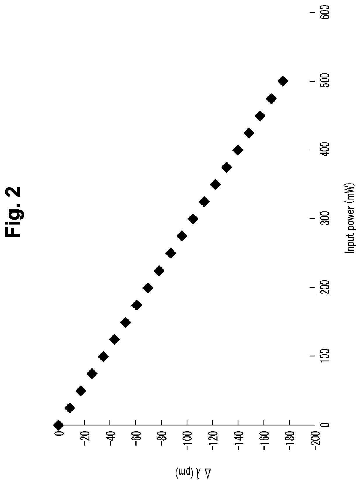
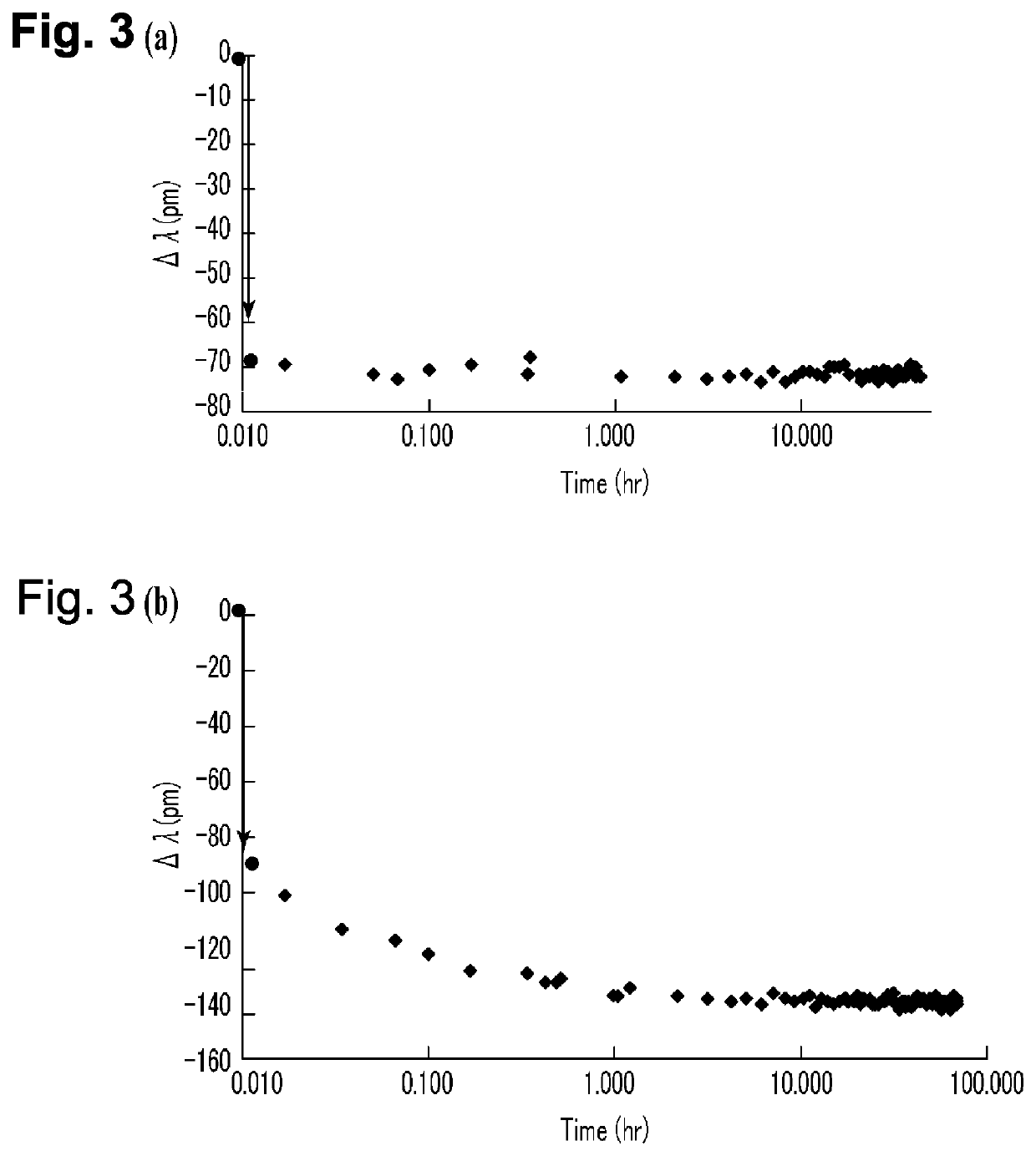
[0040]In the present example, an example will be shown where the following filling resin is applied into the waveguide groove of the optical waveguide circuit. Dimethyl silicone gels KE1056 (refractive index nD(25° C.)=1.414), KLE1055 (refractive index nD(25° C.)=1.426) made of Shin-Etsu Silicone have a refractive index difference of 0.012, and FIG. 4 shows the results of changes (instantaneous change and change over time) in wavelength upon input of high power at the time of filling with a resin obtained by mixing the above gels at 1:1. The dimethyl silicone gels KE1056, KLE1055 can be mixed because the refractive index difference therebetween is within 0.04. When a high power of 200 mW is applied, the wavelength shifts to a shorter wave by −75 pm instantaneously (within ten seconds), but thereafter, the wavelength returns to positive by 12 pm in about ten minutes to one hour. In the case of each of the silicone gels KE1056, KE1055, a catalyst and a thermosetting agent are containe...

example 2

[0042]In the present example, an example will be shown where the following filling resin is applied into the waveguide groove of the optical waveguide circuit. The waveguide groove is filled with fluorine silicone gel X71-8115 (refractive index nD(25° C.)=1.30-1.33) manufactured by Shin-Etsu Chemical Co., Ltd. FIG. 5 shows the results. The fluorine gel has low absorption (loss of 0.1 dB / cm) at a wavelength of 1550 nm, and therefore, even when high power is input, the temperature rise is small and the instantaneous change is small. On the other hand, in the case of filling with fluorine silicone gel X71-8115, when a high power of 200 mW was input, the wavelength instantaneously shifted by −12 pm. Thereafter, the wavelength returned to about 8 pm in about ten hours. This means that the wavelength has returned by about 30%.

[0043]In the present example, the filling resin in the waveguide groove has been described, but the filling resin used in the present example is also applicable betw...

example 3

[0044]In the present example, an example will be shown where the following filling resin is applied into the waveguide groove of the optical waveguide circuit. Upon curing of silicone KER 6200 (refractive index nD(25° C.)=1.500), 5% of phthalate ester dioctyl phthalate (DOP) was added. Phthalate ester DOP is compatible with silicone and can be mixed uniformly. The refractive index of DOP is 1.485 being lower than that of KER 6200, and when high power is input, this DOP diffuses from the light passing portion to the periphery, so that the refractive index of the portion through which light passes increases. Hence the temperature rises instantaneously upon input of high power and the wavelength shifts to a shorter wave by about −50 pm, but thereafter, the wavelength returns to the original value due to the diffusion of DOP. Many various plasticizers have been developed as shown in Table 1 described above, and it is possible to find therefrom the optimum combination of the silicone mat...


PUM

PropertyMeasurementUnit
refractive indexaaaaaaaaaa
poweraaaaaaaaaa
refractive indicesaaaaaaaaaa

Abstract

Provided is an optical waveguide circuit in which the space between waveguides, a waveguide groove, or the space between fibers is filled with a resin where a wavelength shifts to positive (shifts backward) instead of a conventional resin where a wavelength shifts to negative (shifts forward), to return a refractive index having decreased by an instantaneous change to the original refractive index. In the filling resin with which the space between the waveguides, the waveguide groove, the space between the fibers, or the space between the fiber and the waveguide is filled, upon input of light, a refractive index of a portion through which the light passes instantaneously decreases, and then the refractive index gradually increases to compensate the initial decrease in the refractive index.

Description

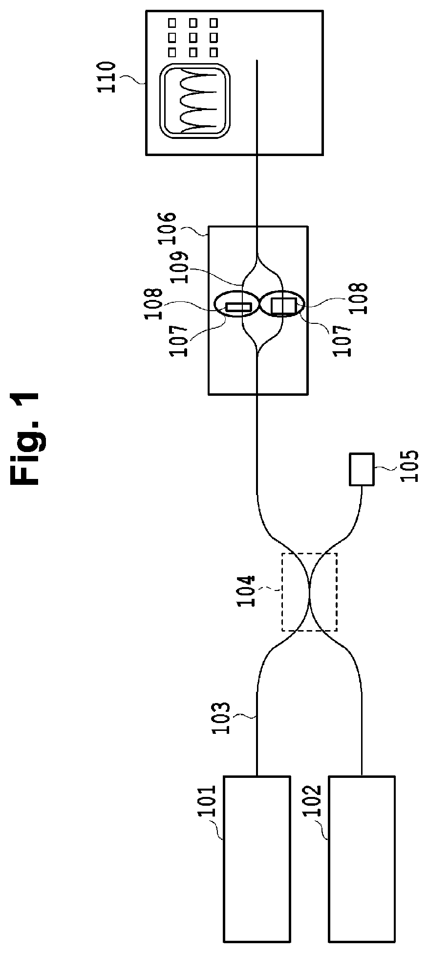
TECHNICAL FIELD[0001]The present invention relates to the field of optical communication using optical fibers and waveguides, and the like, or to the field of visible measurement using optical fibers and waveguides, and particularly relates to a resin with which the space between waveguides, the space between fibers, or a waveguide groove is filled when a high power of 100 mW or more is transmitted to the fibers and the waveguides.BACKGROUND ART[0002]In the field of optical communication, a connector or a mechanical splicer is used to connect fibers. In the mechanical splicer, the space between fibers is filled with a silicone-based matching gel to improve the connection between the fibers. In the case of connection between a fiber and a waveguide, between waveguides, and between fibers, an adhesive is used, and in the case of filling of a groove dug in the waveguide with a wavelength plate or an athermal resin, an adhesive or a resin is used.[0003]However, when input power becomes ...

Claims


Application Information

Patent Timeline
Patent Type & Authority Applications(United States)
IPC IPC(8): G02B6/30G02B6/26C08K5/12
CPCG02B6/30C08K5/12G02B6/262C08L101/12C08L83/04G02B6/4212C08K5/0016C08L23/0853
Inventor HIRABAYASHI, KATSUHIKOKOSHOBU, NOBUTATSUKASAHARA, RYOICHI
Owner NIPPON TELEGRAPH & TELEPHONE CORP
Learn More