
System and method using collaborative learning of interference environment and network topology for autonomous spectrum sharing

a technology of interference environment and network topology, applied in the field of radio access networks, can solve the problems of increasing congestion in the network, preventing dynamic adaptation to supply and demand, overloading the spectrum,

Active Publication Date: 2021-08-19
INTEL CORP
View PDF6 Cites 22 Cited by
  • Summary
  • Abstract
  • Description
  • Claims
  • Application Information

AI Technical Summary

Benefits of technology

The patent text discusses various aspects of radio access networks, including cellular and wireless local area networks. The technical effects of the patent include making intelligent use of network resources, avoiding interference, and improving network mapping. The text also describes various radio communication technologies and standards used in these networks. Overall, the patent aims to provide technical solutions for efficient and effective use of radio networks.

Problems solved by technology

The continual infusion of additional devices, such as sensors, have overloaded the spectrum; breaking the spectrum into rigid exclusively licensed bands, as done previously, may prevent dynamic adaption to the supply and demand of network resources.
The addition of devices and overloading of the spectrum causes increased congestion in the network and correspondingly increases the amount of interference.
This is unlike existing systems, which act in isolation and treat transmissions from other networks as interference and thereby try to avoid the transmissions or treat them as noise.
Moreover, existing systems may be unable to relay packets from an entirely different network or even make a determination of whether or not to relay due to the different nature of the network.
As the physical layer techniques (e.g., the radio access technologies (RATs)) used by the source in the other network may be only partially known or completely unknown to the relaying node in the CIRN, adding an additional layer of complexity to the ability to relay the packets through the CIRN.
In some cases, however, the headers may not be immediately decodable by the CIRN nodes due to differences between the physical layer mechanisms used by the CIRN and those used by the other network.
Alternatively, the classification algorithm may also frame this as a clustering problem, in which data / ACK pairs are clustered according to their source / destination pairs.
For example, too high a transmit power by the relay node may adversely affect other nodes by causing increased interference, thereby offsetting the benefit to the destination node.
The retransmission power may also be posed as a reinforcement learning problem in which the action space is the transmit power and the reward space is the throughput or a proxy to the throughput.
However, scheduling used previously by a node has not taken into account both its own network and neighbor network data to maximize performance of the node while helping a neighboring network to have connectivity by relaying data from an isolated node.
This may be due, at least in part, to the lack of incentives from the neighboring network to compensate for the energy a node in the network uses in relaying packets from and to the neighboring network.
This may increase the difficulty in exploring some of the state spaces.
Two common types of problems in machine-learning are classification problems and regression problems.
Each model develops a rule or algorithm over several epochs by varying the values of one or more variables affecting the inputs to more closely map to a desired result, but as the training dataset may be varied, and is preferably very large, perfect accuracy and precision may not be achievable.

Method used


Image

  • System and method using collaborative learning of interference environment and network topology for autonomous spectrum sharing
  • System and method using collaborative learning of interference environment and network topology for autonomous spectrum sharing
  • System and method using collaborative learning of interference environment and network topology for autonomous spectrum sharing

Examples


example 1

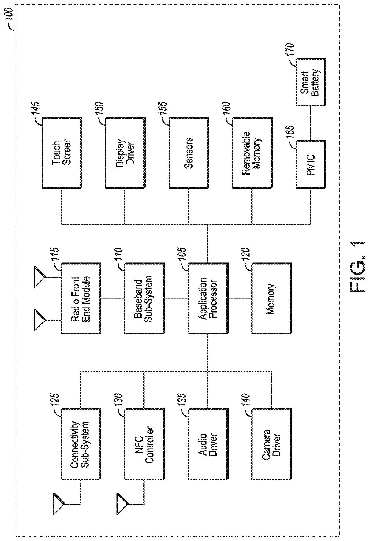
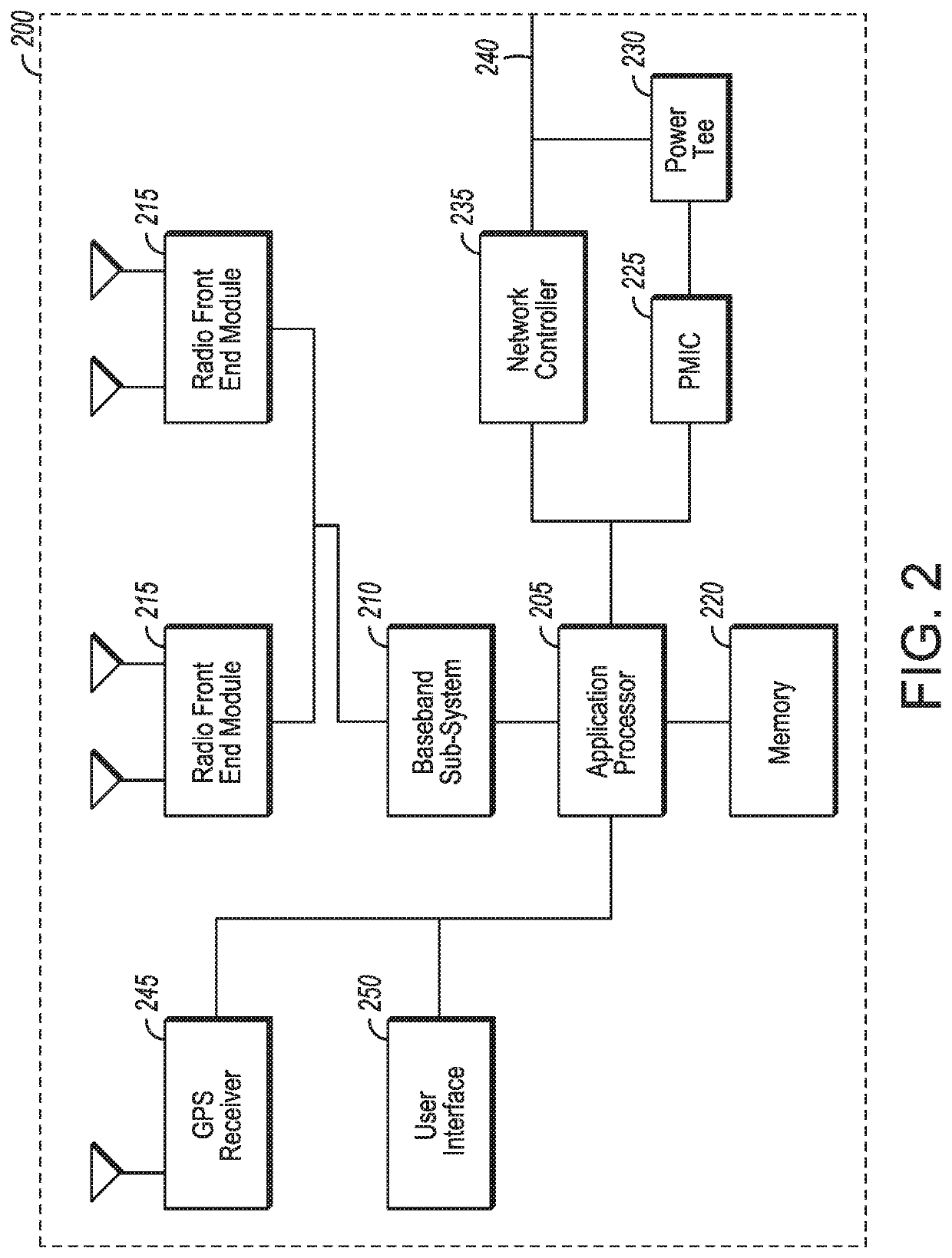
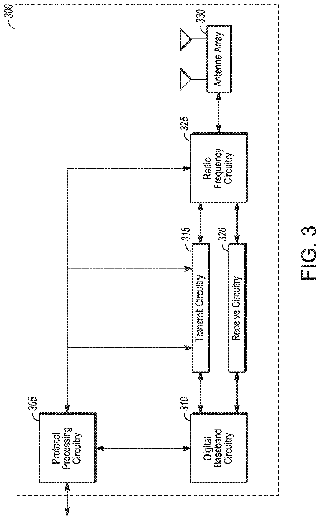
[0223 is an apparatus of a collaborative intelligent radio network (CIRN) node, the apparatus comprising: processing circuitry arranged to: identify whether the CIRN node is within transmission range of a source node of a transmission and within reception range of a destination node of the transmission, the source and destination nodes in a neighboring network from a CIRN network of the CIRN node; schedule a relay of the transmission to the destination node in response to a determination that a relay mode is to relay the transmission, wherein the schedule takes into account performance measurement of the CIRN network and collaboration feedback of performance measurement of the neighboring network; and a memory configured to store at least one machine-learning algorithm to learn how transmissions of the CIRN node impact transmissions of the source and destination node, minimize interference in the neighboring network, or discover and determine topology of the neighboring network.

[022...


PUM


Abstract

Systems and methods of using machine-learning to improve communications across different networks are described. A CIRN node identifies whether it is within range of a source and destination node in a different network using explicit information or a machine-learning classification model. A neural network is trained to avoid interference using rewards associated with reduced interference or retransmission levels in each network or improved throughput at the CIRN node. A machine-learning scheduling algorithm determines a relay mode of the CIRN node for source and destination node transmissions. The scheduling algorithm is based on the probability of successful transmission between the source and destination nodes multiplied by a collaboration score for successful transmission and the probability of unsuccessful transmission of the particular packet multiplied by a collaboration score for unsuccessful transmission.

Description

TECHNICAL FIELD[0001]Aspects pertain to radio access networks (RANs). Some aspects relate to cellular and wireless local area network (WLAN) networks, including Third Generation Partnership Project Long Term Evolution (3GPP LTE) networks and LTE advanced (LTE-A) networks as well as legacy networks, 4th generation (4G) networks and 5th generation (5G) networks. Some aspects relate to autonomous spectrum sharing based on collaborative learning models.BACKGROUND[0002]Network use continues to increase due to both an increase in the types of devices user equipment (UEs) using network resources as well as the amount of data and bandwidth being used by various applications on individual devices, such as video streaming, operating on these UEs. With the explosion of network usage, making intelligent use of the network resources has become increasingly desirable due to the limited availability of bandwidth.BRIEF DESCRIPTION OF THE FIGURES[0003]In the figures, which are not necessarily drawn ...

Claims


Application Information

Patent Timeline
Patent Type & Authority Applications(United States)
IPC IPC(8): H04W72/12H04W24/10H04W24/02H04W88/04H04W72/04H04W16/14G06K9/62G06N3/08
CPCH04W72/1263H04W24/10H04W24/02H04W88/04G06N3/08H04W72/0446H04W16/14G06K9/6262H04W72/1231G06N3/006G06N3/084G06N3/088G06N3/086G06N3/126G06N20/20G06N20/10G06N5/01G06N7/01G06N3/044G06F18/217H04W72/542
Inventor BALAKRISHNAN, RAVIKUMARHIMAYAT, NAGEENLIAO, YITINGARROBO VIDAL, GABRIELDOOSTNEJAD, ROYAKESAVAN, VIJAY SARATHINALLAMPATTI EKAMBARAM, VENKATESANRAMIREZ LOAIZA, MARIASOMAYAZULU, VALLABBAJOSYULA S.SRIKANTESWARA, SRIKATHYAYANI
Owner INTEL CORP
Learn More