Methods and systems for controlling tourniquets
- Summary
- Abstract
- Description
- Claims
- Application Information
AI Technical Summary
Benefits of technology
Problems solved by technology
Method used
Image
Examples
Embodiment Construction
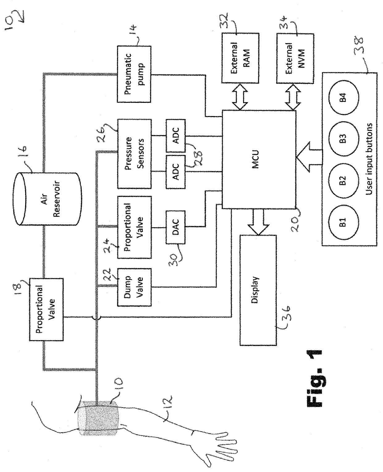
[0061]In FIG. 1 there is shown a block diagram of a system for controlling a tourniquet 10 applied to a limb 12. In this diagram air lines are shown using heavier weights and electrical connections shown using regular weight lines, while wide arrows indicate input / output (I / O) buses.
[0062]The tourniquet 10 is of the inflatable cuff type and can be pressurised by means of a pneumatic pump 14 which feeds an air reservoir 16 to store air under pressure, with a proportional valve 18 being controllable by a microcontroller unit (MCU) 20.
[0063]Air can be released using a dump valve 22 or a proportional valve 24. The proportional valve 24 is primarily used as the controlled deflation mechanism for the tourniquet, while the dump valve 22 is provided for rapid deflation such as in an emergency.
[0064]The pressure of air in the tourniquet 10 is monitored by a plurality of pressure sensors 26 (provided for redundancy in case of failure), whose output is digitised by analog-to digital converters...
PUM
 Abstract
Description
Claims
Application Information
 - R&D
- Intellectual Property
- Life Sciences
- Materials
- Tech Scout
- Unparalleled Data Quality
- Higher Quality Content
- 60% Fewer Hallucinations
Browse by: Latest US Patents, China's latest patents, Technical Efficacy Thesaurus, Application Domain, Technology Topic, Popular Technical Reports.
© 2025 PatSnap. All rights reserved.Legal|Privacy policy|Modern Slavery Act Transparency Statement|Sitemap|About US| Contact US: help@patsnap.com


