
Depth buffer dilation for remote rendering

Active Publication Date: 2021-08-26
MICROSOFT TECH LICENSING LLC
View PDF0 Cites 0 Cited by
  • Summary
  • Abstract
  • Description
  • Claims
  • Application Information

AI Technical Summary

Benefits of technology

This patent is about improving the transmission and projection of color images for goghraphic display devices. By generating a depth buffer that distinguishes between different content regions and eliminates non-essential depth discontinuities, the patent achieves more efficient data transmission and improved performance of the computing architecture. This results in better user experience with the display device. Additionally, by reducing the amount of data required to be transmitted, the patent reduces bandwidth usage.

Problems solved by technology

Often, however, there is a time lag or latency between when the remote service generates the image and when the HMD actually displays the image.
Additionally, with traditional systems, the process of encoding and compressing the depth buffer often requires a substantial amount of computing resources.
Indeed, one of the properties of video compression is that depth discontinuities (i.e. large changes in depth between neighboring depth values) are quite difficult to encode.
Accordingly, notwithstanding the benefits that arise from using remote rendering, there exists many problems with remote rendering.
One problem includes inefficiencies on the remote server-side concerning the compression and transmission of potentially highly detailed and computationally expensive color images or holograms and corresponding depth buffers that are transmitted over a network.
Indeed, traditional systems consume large amounts of computing power to process discontinuities in depth buffers.
Another problem includes inefficiencies on the HMD-side once the HMD receives the color images and depth buffers and needs to perform reprojections to correct those images' poses.

Method used


Image

  • Depth buffer dilation for remote rendering
  • Depth buffer dilation for remote rendering
  • Depth buffer dilation for remote rendering

Examples


Embodiment Construction

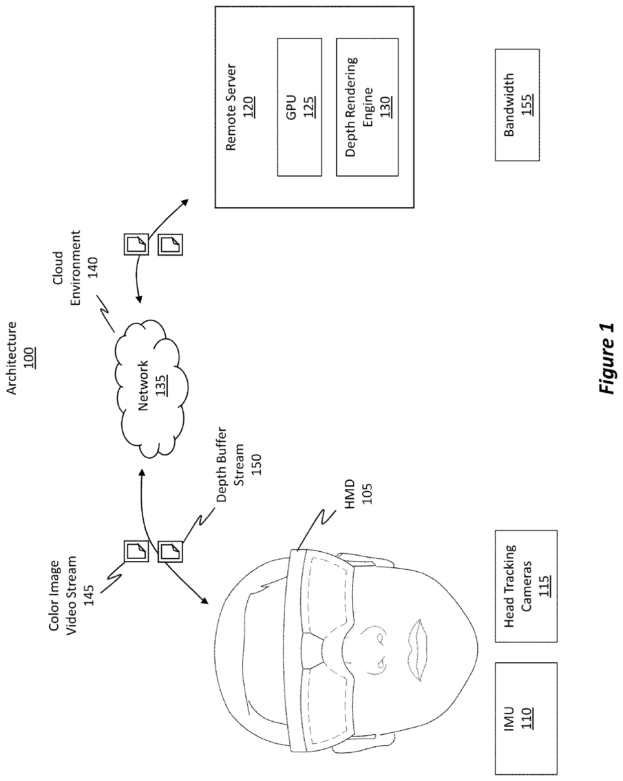
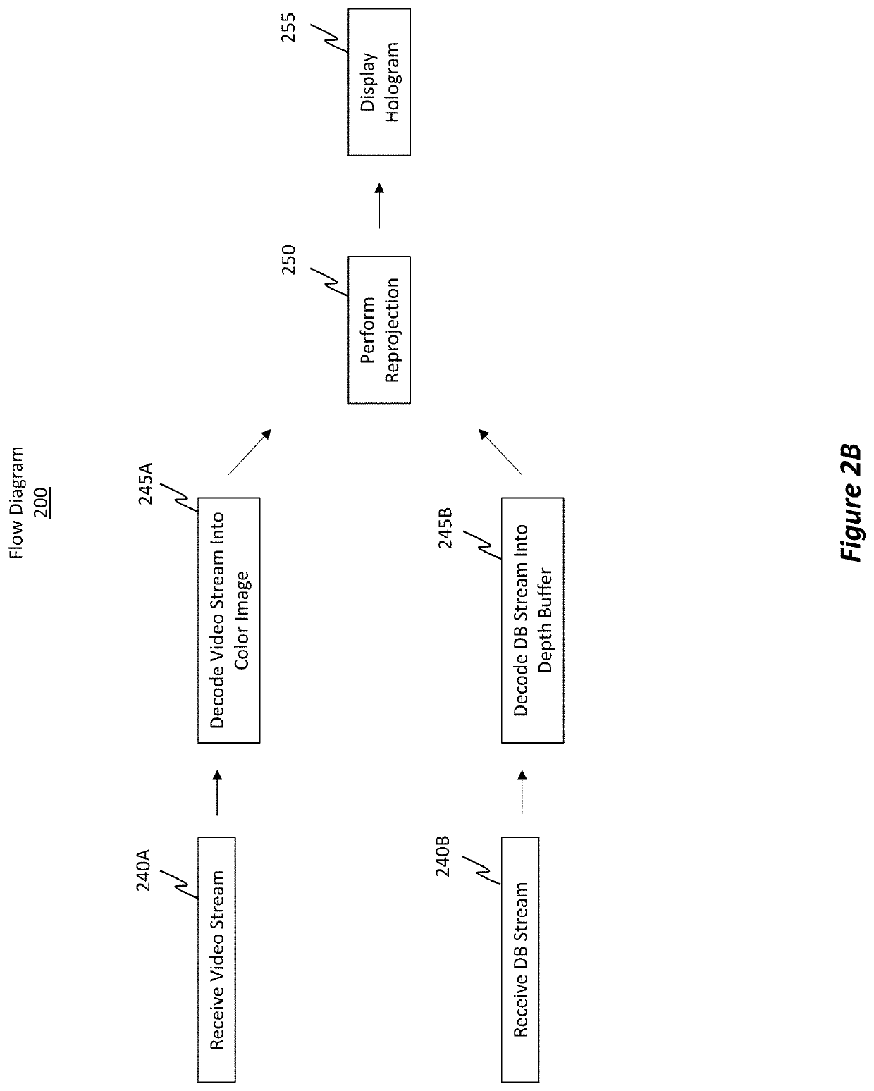
[0025]Embodiments disclosed herein improve the transmission efficiency of color images (i.e. holograms) between a remote rendering service and an HMD as well as improve the reprojection efficiency of those color images once they are received by the HMD.

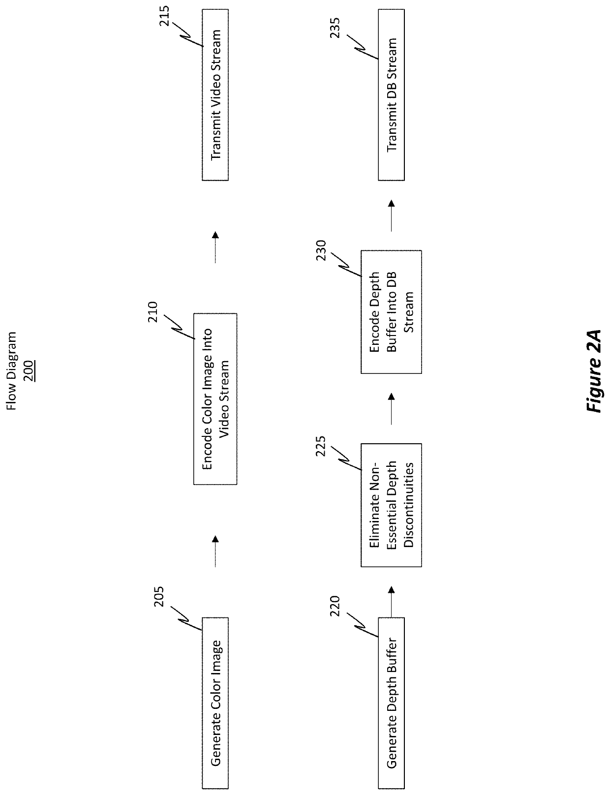
[0026]In some embodiments, a color image is generated to include a first content region, a second content region, and an overlap region where the second content region at least partially overlaps the first content region. A depth buffer includes depth values for the pixels in the color image. The depth buffer also distinguishes between a first set of depth values for the first content region, a second set of depth values for the second content region, and a third set of depth values for a non-content region included in the color image. The embodiments then identify essential depth discontinuities and non-essential depth discontinuities in the depth buffer. “Essential” depth discontinuities are depth discontinuities located within the ...


PUM


Abstract

Techniques for improving remote rendering and reprojection are disclosed herein. A color image is generated, where this color image includes overlapping content regions. A depth buffer is generated for the color image and includes depth values for the pixels in the color image. The depth buffer includes both essential and non-essential depth discontinuities. While preserving the essential depth discontinuities, the non-essential depth discontinuities are eliminated from the depth buffer. New non-essential discontinuities are prevented from being included in the final version of the depth buffer. The color image is encoded into a color image video stream, and the modified depth buffer is encoded into a depth buffer stream. The color image video stream and the depth buffer stream are then transmitted to a remotely located HMD. The HMD then reprojects the color image based on the depth values in the depth buffer.

Description

BACKGROUND[0001]Mixed-reality (MR) systems / devices include virtual-reality (VR) and augmented-reality (AR) systems. Conventional VR systems create completely immersive experiences by restricting users' views to only virtual images rendered in VR scenes / environments. Conventional AR systems create AR experiences by visually presenting virtual images that are placed in or that interact with the real world. As used herein, VR and AR systems are described and referenced interchangeably via use of the phrase “MR system.” As also used herein, the terms “virtual image,”“virtual content,”“color image,” and “hologram” refer to any type of digital image rendered by an MR system. Furthermore, it should be noted that a head-mounted device (HMD) typically provides the display used by the user to view and / or interact with holograms provided within an MR scene / environment.[0002]An MR system's HMD typically includes a head tracking camera system having one or more head tracking camera(s) and an ine...

Claims


Application Information

Patent Timeline
IPC IPC(8): G06T15/40G06T15/00G06F3/01
CPCG06T15/405G06F3/012G06T15/005H04N13/128G02B27/017G06T2207/10028G02B2027/014H04N13/117G06T5/70
Inventor VOSS-WOLFF, CHRISTIAN
Owner MICROSOFT TECH LICENSING LLC
Learn More