
Method of pulsed laser irradiation with reduced thermal damage

a pulsed laser and thermal damage technology, applied in the field of pulsed laser irradiation with reduced thermal damage, can solve the problem of reducing the voxel quality

Pending Publication Date: 2021-08-26
UNIV OF SOUTHAMPTON
View PDF0 Cites 0 Cited by
  • Summary
  • Abstract
  • Description
  • Claims
  • Application Information

AI Technical Summary

Benefits of technology

The patent describes a method of delivering optical energy to a substrate using pulses of femtosecond duration. The pulses are organized into two groups, with the first group containing up to three pulses and the second group containing the remaining pulses. The energy of the pulses is controlled so that the first group has a higher energy per pulse than the second group. This approach allows for more precise and controlled shaping of the optical energy at the substrate, improving the efficiency and precision of the process.

Problems solved by technology

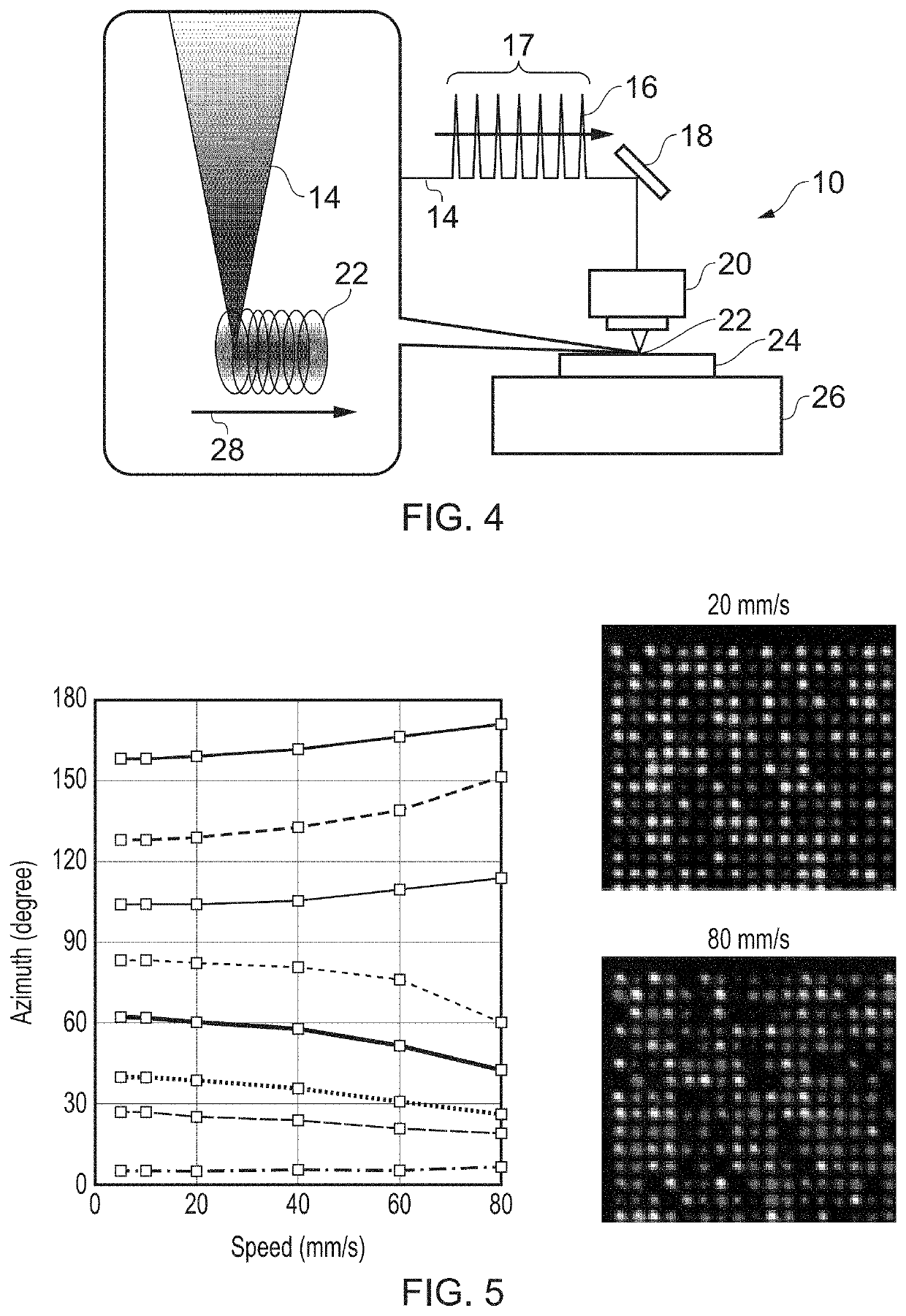
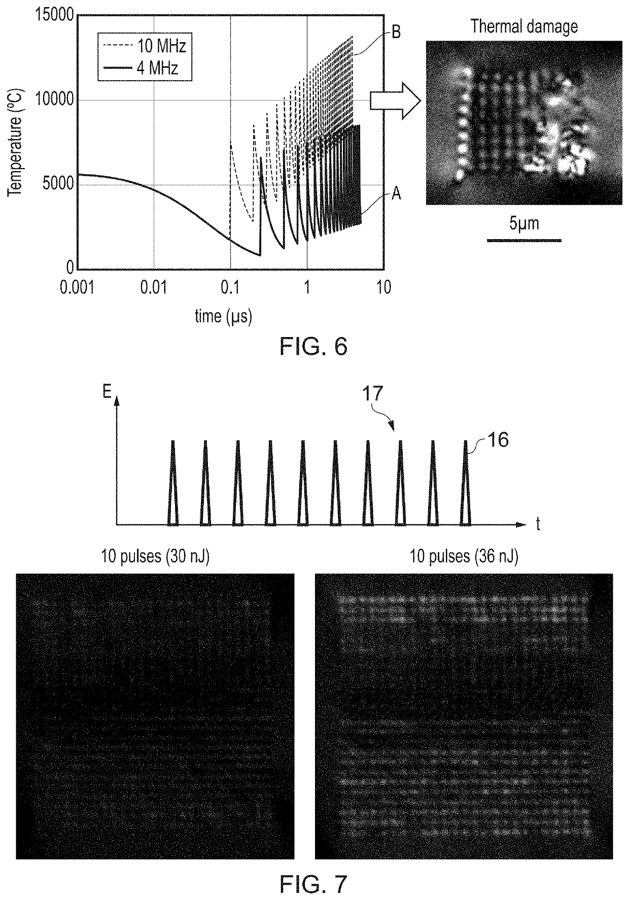
The pulse delivery time per voxel depends on the repetition rate of the laser pulses, but if this is increased too much in order to reduce the time, thermal damage occurs in the substrate which reduces the voxel quality.

Method used


Image

  • Method of pulsed laser irradiation with reduced thermal damage
  • Method of pulsed laser irradiation with reduced thermal damage
  • Method of pulsed laser irradiation with reduced thermal damage

Examples


Embodiment Construction

[0025]Aspects and features of certain examples and embodiments are discussed / described herein. Some aspects and features of certain examples and embodiments may be implemented conventionally and these are not discussed / described in detail in the interests of brevity. It will thus be appreciated that aspects and features of methods discussed herein which are not described in detail may be implemented in accordance with any conventional techniques for implementing such aspects and features.

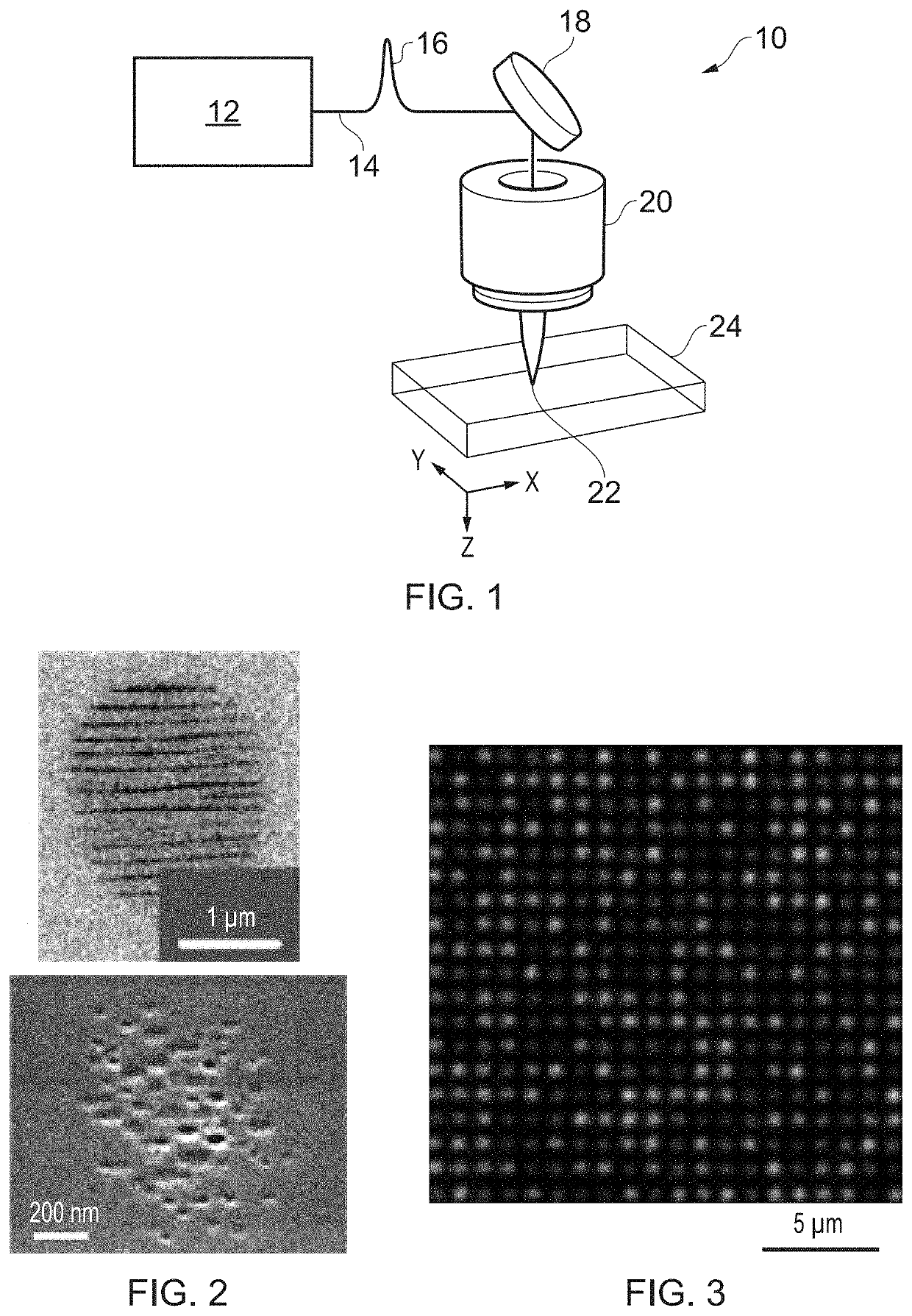
[0026]Embodiments of the present disclosure relate to methods for irradiating a substrate with laser pulses. As a particular example, the fabrication of nanostructured optical elements will be discussed. This application uses pulsed laser irradiation to form birefringent nanostructures in optical elements, for example elements for optically storing data or elements that use the geometric phase effect to modify the polarisation and / or phase of light. In the present disclosure, the term “optical eleme...


PUM

PropertyMeasurementUnit
first energyaaaaaaaaaa
energyaaaaaaaaaa
second energyaaaaaaaaaa

Abstract

A method of delivering optical energy to a substrate comprises applying a temporal group of optical pulses to a region of the substrate, wherein the temporal group comprises twenty or fewer pulses of a femtosecond pulse duration, arranged as a first subgroup of pulses comprising up to three pulses followed by a second subgroup of pulses comprising the remaining pulses in the temporal group; and wherein energies of the pulses are controlled such that pulses in the first subgroup have a first energy per pulse and pulses in a second subgroup of pulses have a second energy per pulse which is less than the first energy.

Description

BACKGROUND OF THE INVENTION[0001]The present invention relates to a method of irradiating or exposing a substrate to pulsed laser radiation, such as to form birefringent nanostructures, that allows a reduction in thermal damage of the substrate.[0002]A class of optical materials comprises transparent substrates internally structured with anisotropic nanostructures that give birefringent properties to the material. Formation of such anisotropic sub-wavelength structures was first reported in 1999 [1]. The nanostructure is formed by irradiating the substrate material, such as silica glass, with ultrashort pulses of laser light. Nanostructuring can be used to write data into the substrate, enabling highly effective data storage [2]. A nanostructure is made up of individual nanopores or voids with an anisotropic shape, or assembled and aligned into a grating format. These features give the nanostructure an overall birefringence with an optical retardance value and a slow axis of birefri...

Claims


Application Information

Patent Timeline
Patent Type & Authority Applications(United States)
IPC IPC(8): H01S3/00B23K26/0622
CPCH01S3/0057B23K26/0624B23K26/355B23K2103/54B82Y20/00B82Y40/00G02B5/3083H01S3/0007
Inventor SAKAKURA, MASAAKIYU, YANHAOKAZANSKY, PETERWANG, LEI
Owner UNIV OF SOUTHAMPTON
Learn More