
Integrated photonic microwave sampling system

a microwave sampling and integrated technology, applied in the field of photonic systems, can solve problems such as system limitations

Inactive Publication Date: 2021-08-26
IMRA AMERICA
View PDF0 Cites 3 Cited by
  • Summary
  • Abstract
  • Description
  • Claims
  • Application Information

AI Technical Summary

Benefits of technology

The patent describes a microwave receiver system that uses optical components to analyze microwave signals. The system includes a dual comb generator and two wavelength division multiplexing systems to separate and analyze the microwave signal. The system also includes optical-to-electrical converters to record the optical interference between the two combs. The system can control or monitor the optical phase of the interference signals. The technical effect of this invention is to provide a more accurate and reliable method for analyzing microwave signals and to improve the performance of microwave receivers.

Problems solved by technology

Such systems can have limitations.

Method used


Image

  • Integrated photonic microwave sampling system
  • Integrated photonic microwave sampling system
  • Integrated photonic microwave sampling system

Examples


Embodiment Construction

[0023]Overview

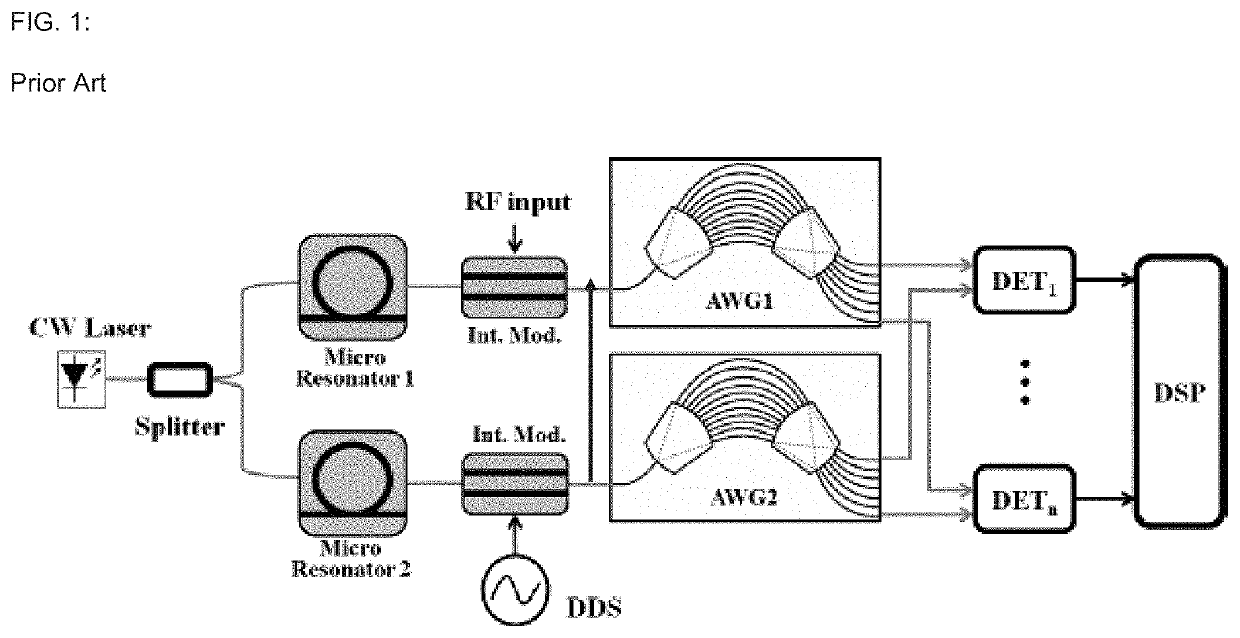
[0024]FIG. 1 schematically illustrates a prior art photonic microwave channelization system as disclosed in U.S. Pat. No. 10,498,453 (“the '453 patent”), which is incorporated in its entirety by reference herein. In this system, broadband microwave signals are channelized into spectral slices and detected via heterodyning in the optical domain via a two-comb system. However, the phase information of the microwave signals was lost in the system, as no provisions for phase control or phase recording between the two optical combs was implemented. Thus, the system was only used for RF frequency measurements, but not for full characterization of the amplitude and phase of microwave signals.

[0025]Another photonic RF signal receiver or analyzer utilizing photonic channelization based on wavelength-division-multiplexing (WDM) was, for example, discussed in X. Xie et al., “Broadband photonic RF channelization based on coherent optical frequency combs and I / Q demodulators,” IEEE...


PUM


Abstract

Examples of systems and methods for integrated photonic broadband microwave receivers and transceivers are disclosed based on integrated coherent dual optical frequency combs. In some cases, when the system is configured as a receiver, the microwave spectrum of the input signal can be sliced into several spectral segments for low-bandwidth detection and analysis. In some cases, when the system is configured as a transmitter, multiple radio frequency (RF) carriers can be generated, which can be coherently added or encoded independently for transmission of individual microwave bands. In some systems, the optics-related functionalities can be achieved via integrated optic technology, for example, based on silicon photonics, providing tremendous possibilities for mass-production with significantly reduced system footprint.

Description

CLAIM OF PRIORITY[0001]This application claims the benefit of priority to U.S. Provisional Appl. Nos. 62 / 981,852 filed on Feb. 26, 2020, which is incorporated in its entirety by reference herein.BACKGROUNDField[0002]The present disclosure relates generally to photonic systems and more particularly to integrated microwave photonic sampling systems.DESCRIPTION OF THE RELATED ART[0003]Radio frequency (RF) signal analyzers utilizing photonic channelization based on wavelength-division-multiplexing (WDM) have been developed. Time-division-multiplexing (TDM)-based microwave channelizers have also been developed. Optical sampling systems for RF signals have also been developed. Such systems can have limitations.SUMMARY[0004]In certain embodiments, a microwave receiver system comprises at least one electro-optic modulator configured to receive a microwave signal under test (SUT) and to modulate the SUT onto at least one comb line of a first optical frequency comb having a first repetition r...

Claims


Application Information

Patent Timeline
IPC IPC(8): H04B10/073H04J14/02
CPCH04B10/073H04B2210/006H04J14/0227H04B10/2575
Inventor FERMANN, MARTIN E.
Owner IMRA AMERICA
Learn More