Wood chipper with drum speed monitoring system and centrifugal clutch

a technology of drum speed monitoring and clutch, which is applied in the field of wood chippers, can solve the problems of affecting the rotational speed of the drum, thicker wood pieces such as tree trunks, and the difficulty of cutting blades on the rotating drum to process

Active Publication Date: 2021-09-02
ALAMO GROUP
View PDF4 Cites 2 Cited by
  • Summary
  • Abstract
  • Description
  • Claims
  • Application Information

AI Technical Summary

Benefits of technology

[0007]The presently disclosed wood chipper includes a monitoring system which continuously tracks the speed of rotation of the drum. If the drum speed drops below a pre-set or pre-determined threshold speed because a larger, thicker piece of wood is being processed, the monitoring system will automatically reduce the power that is delivered by the machine's engine. The engine is operatively engaged with a drive assembly which powers the drum by way of a drive shaft. When the engine slows down, the speed of rotation of the drive shaft is reduced. The drive assembly includes a centrifugal clutch which is operatively engaged with the drive shaft. When the drive shaft rotation slows to below a threshold value, the centrifugal clutch will disengage and the drive assembly will stop rotating the cutting drum. It is then safe for an operator to reach in and clear any jammed debris from the drum housing. Once the debris is cleared, the operator will increase the speed of the engine to beyond the necessary threshold speed, so as to reengage the centrifugal clutch. Reengaging the centrifugal clutch will actuate the drive assembly which in turn will cause the drum in the drum housing to rotate once again. The presently disclosed wood chipper will automatically cut power to the cutting drum in the event that the drum becomes locked up by larger, thicker wood pieces or by debris accumulating in the drum housing. The drum will stop rotating and, because the drive assembly is effectively automatically disengaged, it is safe for an operator to manually clear debris from the drum housing. The presently disclosed machine therefore reduces the tendency for the engine and drive assembly to become damaged during processing of larger thicker pieces of wood. The presently disclosed machine also reduces the likelihood that the operator might be injured by reaching into the machine to clear debris blockages that have significantly slowed or jammed the rotating drum.
[0011]In one embodiment the drive assembly includes an engine that drives a drive shaft which is operatively engaged with the drum; and the monitoring system further includes a processor provided with programming for calculating a ratio of the speed of rotation of the drum relative to a speed of rotation of the drive shaft. In one embodiment the release mechanism is a centrifugal clutch that is movable between an engaged position and a disengaged position; and when the centrifugal clutch is engaged the drum rotates, and when the centrifugal clutch is disengaged, the drum stops rotating. In one embodiment the monitoring system includes a controller operably connected to a sensor, the controller being configured to control an operation of the rotatable drum based on input from the sensor and detection of a drop in a speed of rotation of the rotatable drum. In one embodiment the controller is configured to stop rotation of the rotatable drum if the speed of rotation of the rotatable drum drops below a threshold value. In one embodiment the drive assembly includes an engine operably engaged with the rotatable drum via a centrifugal clutch, wherein said engine is operatively controlled by controller, and when the speed of rotation of the rotatable drum drops below the threshold value, the controller disengages the centrifugal clutch by reducing power generated by the engine.
[0013]In another aspect, an exemplary embodiment of the present disclosure may provide a method of controlling a material reduction device comprising feeding material to be reduced in size toward a reducing mechanism; rotating the reducing mechanism; reducing the material with the rotating reducing mechanism; detecting a speed of rotation of the rotating reducing mechanism; controlling a drive assembly that drives the rotation of the rotating reducing mechanism based on the detected speed of rotation; and causing the reducing mechanism to cease rotating when the speed of rotation drops below a threshold value while the rotating reducing mechanism is reducing material.

Problems solved by technology

Larger, thicker pieces of wood, such as tree trunks, on the other hand, are more difficult for the cutting blades on the rotating drum to process.
As a result, while cutting thicker pieces of wood, the rotation of the drum may be affected.
In particular, larger, thicker pieces of wood may slow the speed of rotation of the drum quite significantly.
Since the drum is being driven by the drive assembly which in turn is powered by the engine, having the wood slow the rotation of the drum down significantly can have an adverse effect on the engine and on the drive assembly.
In some instances, the larger, thicker pieces of wood can actually jam the drum and prevent it from rotating.
This may be extremely dangerous for the operator of the wood chipper because a person's first instinct tends to be to try and clear the debris that is jamming the drum rotation.
If the operator unthinkingly tries to clear the jam and succeeds, he or she may be injured when the drum suddenly starts to rotate again because the drive assembly is still delivering power to the drum.
The presently disclosed machine also reduces the likelihood that the operator might be injured by reaching into the machine to clear debris blockages that have significantly slowed or jammed the rotating drum.
This may occur, for example, if debris from material being reduced in size by the cutter blades on the drum clogs the machine and slows rotation of the drum.

Method used


Image

  • Wood chipper with drum speed monitoring system and centrifugal clutch
  • Wood chipper with drum speed monitoring system and centrifugal clutch
  • Wood chipper with drum speed monitoring system and centrifugal clutch

Examples


Embodiment Construction

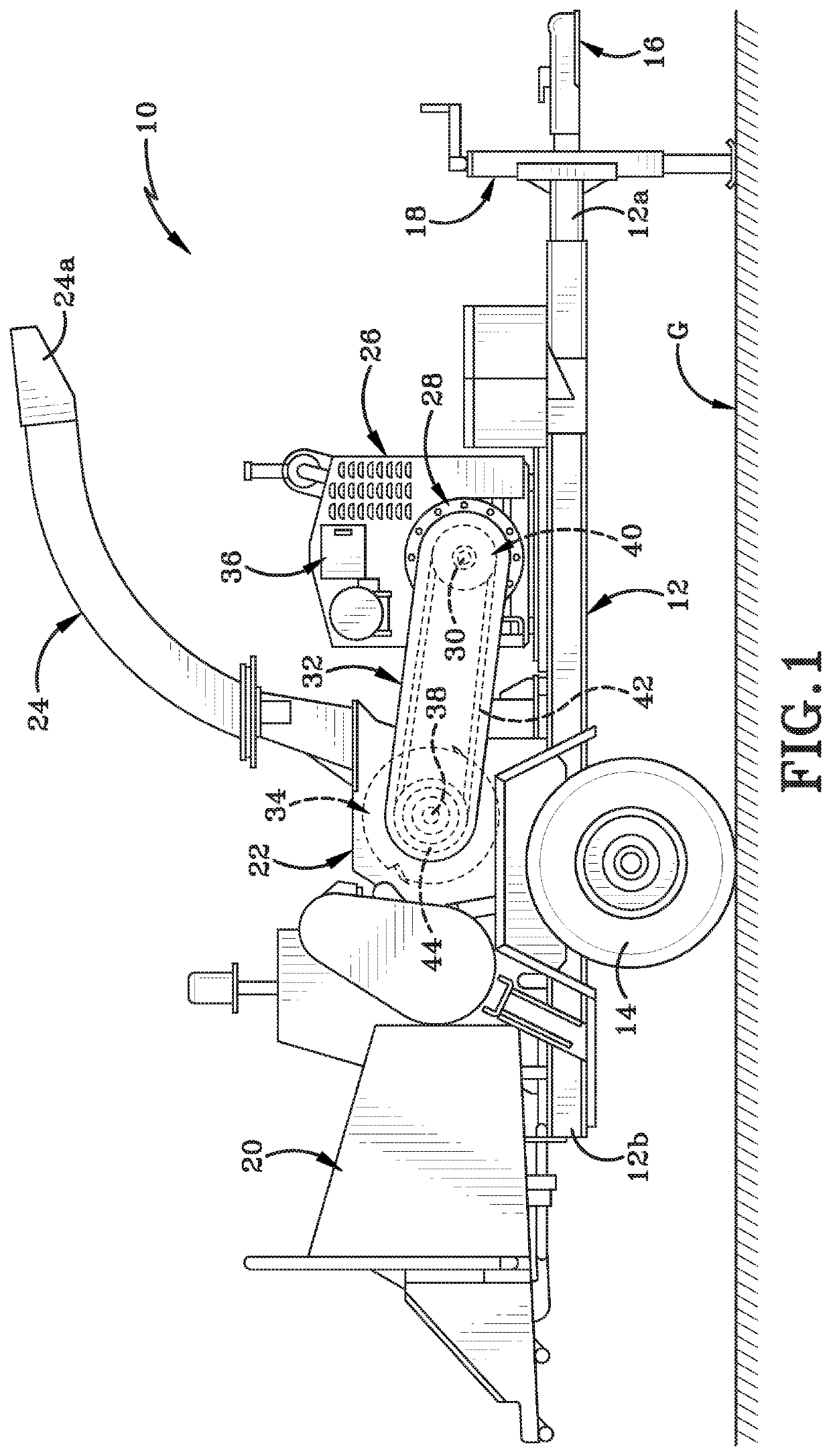
[0031]Referring to FIGS. 1-6, there is shown an apparatus for reducing the size of pieces of wood such as tree trunks and tree limbs to wood chips. The apparatus or wood chipper is indicated herein by the reference number 10. Wood chipper 10 as illustrated herein is exemplary of an apparatus for chipping wood. Wood chipper 10 as illustrated as being configured to be able to be towed behind a vehicle. Furthermore, as illustrated, wood chipper 10 is of a size and configuration suitable for having wood materials fed into the same by hand or by a small piece of auxiliary equipment.

[0032]Wood chipper 10 includes a frame 12 upon which are mounted at least one pair of wheels 14 for moving the frame 12 across the ground “G”. A hitch assembly 16 and a landing gear 18 are also provided on frame 12. Hitch assembly 16 is provided on a front end 12a of frame 12 and enables frame 12 to be operatively engaged with a towing vehicle (not shown). Landing gear 18 is engaged with frame 12 rearwardly of...


PUM


Abstract

A wood chipper having a rotatable drum configured to reduce the size of wood fed into the wood chipper; a sensor configured to sense a speed of rotation of the rotatable drum; and a controller operably connected to the sensor. The controller is configured to cut power to the rotatable drum when the speed of rotation of the rotatable drum drops below a pre-set threshold value. The controller is operably engaged with a centrifugal clutch that is engaged to enable the rotatable drum to be rotated. When the speed of drum rotation drops below the threshold value because debris is slowing down rotation of the drum, the centrifugal clutch is disengaged by dropping engine speed. Disengagement of the centrifugal clutch cuts power to the drum and rotation thereof ceases so that the debris may be cleared.

Description

CROSS-REFERENCE TO RELATED APPLICATIONS[0001]This application claims the benefit of U.S. Provisional Patent Application No. 62 / 983,976, filed Mar. 2, 2020, the entire specification of which is incorporated herein by reference.TECHNICAL FIELD[0002]This application is directed to equipment used to reduce larger pieces of wood into smaller pieces of wood. More particularly, the disclosure relates to wood chippers, including self-propelled, towable and handfed wood chippers. Specifically, the disclosure is directed to a wood chipper which has a monitoring system for tracking the speed of rotation of the drum used to reduce wood material. The wood chipper also includes a centrifugal clutch that stops drum rotation if the monitored speed drops below a threshold value.BACKGROUNDBackground Information[0003]Wood chippers are machines that are used to cut and chop tree trunks, branches, smaller limbs, and brush into chips. The larger pieces of wood are introduced into the machine through an i...

Claims


Application Information

Patent Timeline
Patent Type & Authority Applications(United States)
IPC IPC(8): B02C18/22A01G3/00B02C25/00
CPCB02C18/2266B02C25/00A01G3/002B02C2018/164B02C18/24B02C18/16B27L11/00B27L11/005B27L11/02B27L11/08
Inventor SIMON, DANIEL C.ATKINSON, TREVOR JAMESHADANEK, MICHAEL THOMASELLIS, CASSANDRA JEANSCHAAF, ELIZABETH ANN
Owner ALAMO GROUP
Why Eureka
Try Eureka