

Production of hydrocarbon fuels from waste plastic
- Summary
- Abstract
- Description
- Claims
- Application Information
AI Technical Summary
Benefits of technology
Problems solved by technology
Method used
Image

Examples
first embodiment
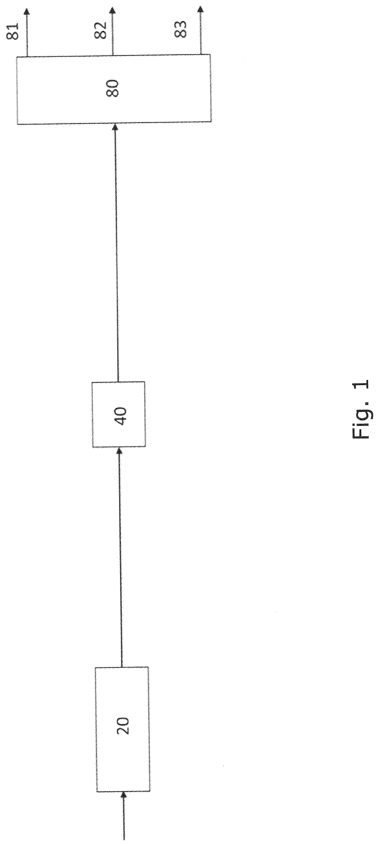
[0282]FIG. 1 illustrates the invention comprising a primary cracking reactor (20) capable of transforming at least one plastic material into a first hydrocarbon fluid being a gas by primary cracking. The first hydrocarbon fluid is directed via the fluid connection to a catalytic hydrogenation reactor (40) capable of transforming the first hydrocarbon fluid to a second hydrocarbon fluid by catalytic hydrogenation. The second hydrocarbon fluid is directed via the fluid connection to a fractional separator (80) for fractional separation of the second hydrocarbon fluid into three products being a light fraction (81), a medium fraction (82) and a heavy fraction (83).
second embodiment
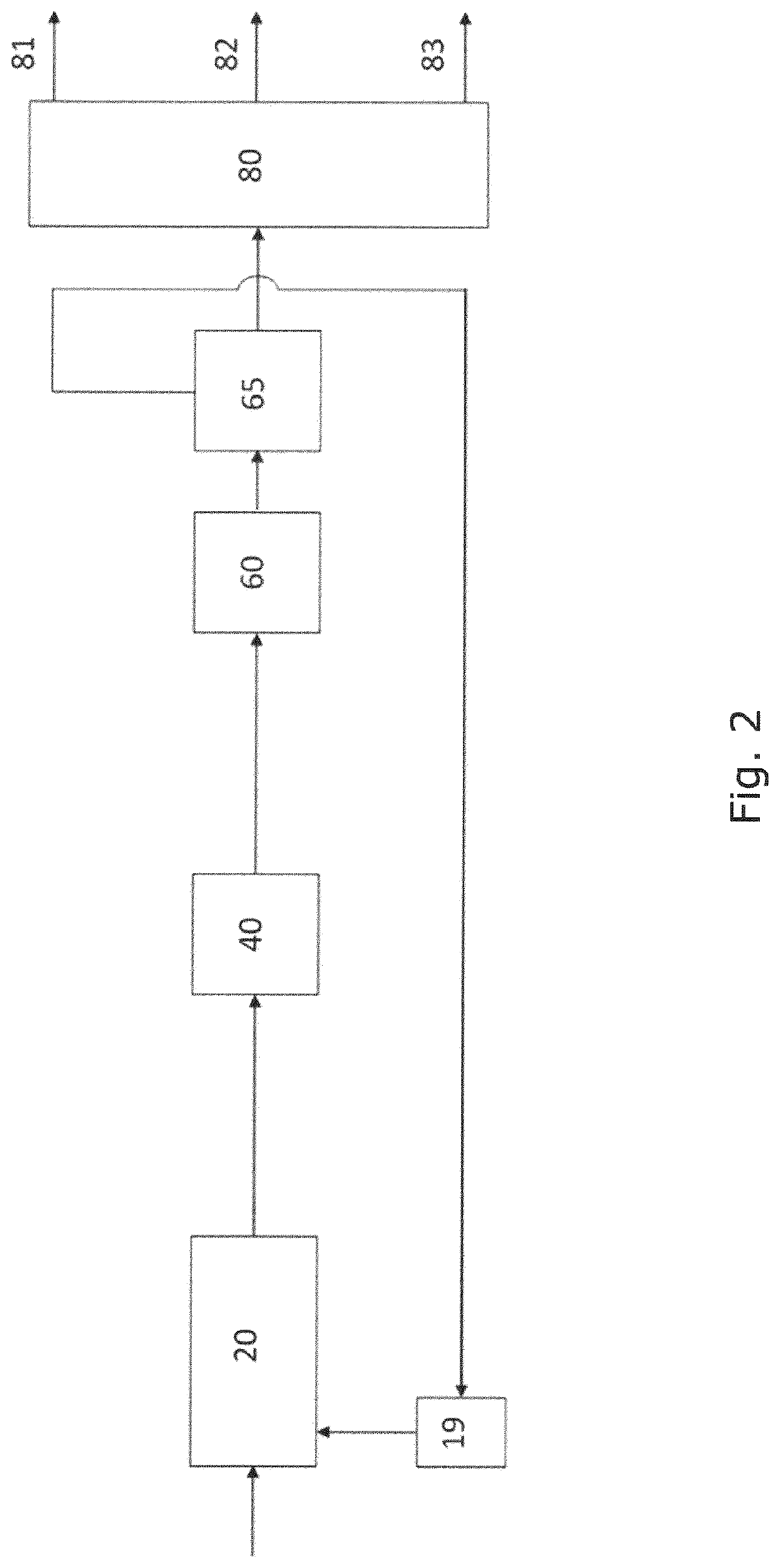
[0283]FIG. 2 illustrates the invention comprising a primary cracking reactor (20) followed by a catalytic hydrogenation reactor (40). The waste plastic is fed to the primary cracking reactor (20) producing a first hydrocarbon fluid being a gas. The first hydrocarbon fluid is then exposed to catalytic hydrogenation (40) forming a second hydrocarbon fluid. In an alternative embodiment, a filter such as illustrated in FIG. 8 (27) at an outlet of the primary cracking reactor (20) is present (not shown in FIG. 2). After catalytic hydrogenation (40), the hydrocarbon fluid is exposed to condensation in a condenser (60) and separation in a post-condensation separator (65) resulting in a first non-condensable gas and a first hydrocarbon liquid as the second hydrocarbon fluid to enter the fractional separator. The first hydrocarbon liquid is fed to a fractional separator (80) and being separated into a light fraction (81), a medium fraction (82) and a heavy fraction (83).
[0284]In an alternati...
third embodiment
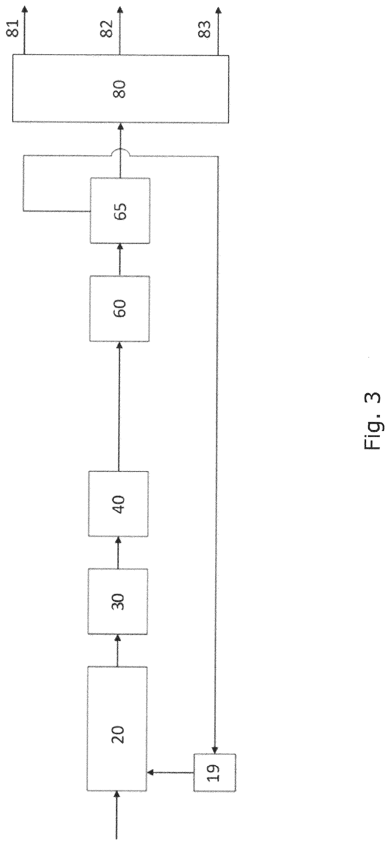
[0287]FIG. 3 illustrates the invention, where waste plastic is fed into a primary cracking reactor (20). The hydrocarbon fluid exiting the primary cracking reactor (20), being a gas, is then exposed to a catalytic cracking in a pre-hydrogenation catalytic cracking reactor (30) before the first hydrocarbon fluid is catalytic hydrogenated in a catalytic hydrogenation reactor (40). The resulting hydrocarbon fluid is then condensed in a condenser (60) and separated in a post-condensation separator (65) a first non-condensable hydrocarbon gas and a first hydrocarbon liquid. The first hydrocarbon liquid is fed to a fractional separator (80) for fractional separation of the second hydrocarbon fluid into three products being a light fraction (81), a medium fraction (82) and a heavy fraction (83). The first non-condensable hydrocarbon gas is re-circulated to a gas burner (19) heating up the primary cracking reactor (20).
[0288]Plastic is fed to the primary cracking reactor (20) producing a hy...
PUM
 Abstract
Description
Claims
Application Information