
Method for heating a blast furnace stove

Inactive Publication Date: 2016-05-26
LINDE AG
View PDF5 Cites 0 Cited by
  • Summary
  • Abstract
  • Description
  • Claims
  • Application Information

AI Technical Summary

Benefits of technology

The patent describes a method for heating a blast furnace stove which reduces CO2 emissions from integrated steel plants. The method combines flue gas recycle with oxy-fuel combustion to concentrate CO2 in a way that makes it easier to capture. The technical effect of this method is significant reduction in CO2 emissions from the steel plants.

Problems solved by technology

The combustion of such additional fuel leads to larger overall emissions of carbon dioxide from the plant, and is therefore not desirable.
Such methods may in some cases render peak flame temperatures high enough to damage the refractory material of the stove, and it may be necessary for example to supply an excess air rate to suppress the flame temperature.
All the above-described methods add complexity to the process and require costly equipment.
It is approaching the limits of thermodynamic efficiency, which is why it is difficult to reduce energy consumption relative to current best operating practices.
Furthermore, the energy consumed in iron making is the dominant factor determining the carbon consumption of the integrated steel making process, and therefore the emissions of carbon dioxide.
However, such separation is relatively expensive.
In addition to the problem of high peak temperatures mentioned above, flame temperatures or heat input rates which are too low will result in unusually long heating cycles, which is undesirable, as such cycles will result in low blast temperatures.

Method used


Image

  • Method for heating a blast furnace stove
  • Method for heating a blast furnace stove
  • Method for heating a blast furnace stove

Examples


Embodiment Construction

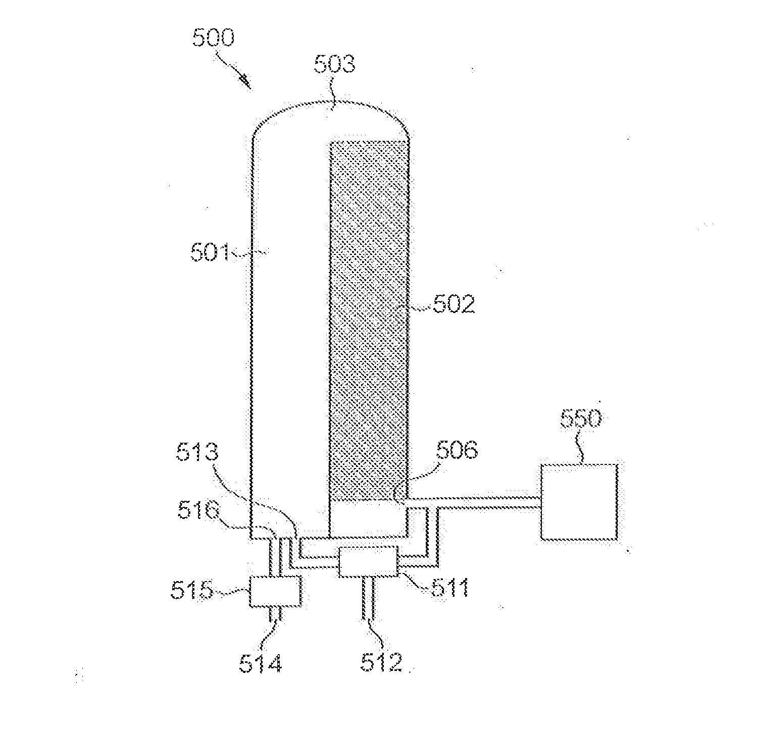
[0030]It is preferred, in the context of the present invention, to heat the stove with blast furnace top gas, as described above. It is furthermore preferred to use top gas from a blast furnace to which blast air is provided from the stove. This allows for the arrangement of the stove near the blast furnace, is energy efficient and leads to low total emissions from the plant.

[0031]However, it is to be understood that the present invention can be equally advantageously applied to stoves heated with other low-grade fuels. By way of example, typical chemical compositions (percentage values) and lower heating values (LHV) are provided in Tables I and II, respectively, for blast furnace top gas and converter off-gas.

TABLE 1N2H2OO2H2COCO2CH4CmHnTop gas52.50.552.323.520——1.15Off-gas17.20.12.564.515.6——0.1

TABLE 2LHV (MJ / Nm3)LHV (MJ / kg)Top gas3.22.4Off-gas6.38.4

[0032]According to the present invention, the stove is heated with a gaseous fuel the LHV value of which is not higher than 9 MJ / Nm3...


PUM


Abstract

A method for heating a blast furnace stove includes combining flue gas recycling and oxy-fuel combustion for concentrating CO2 for facilitating carbon capture and reducing CO2 emissions from a plant operatively associated with the stove. Top gas from a blast furnace associated with the stove may be the fuel for the stove.

Description

BACKGROUND OF THE INVENTION[0001]The present invention relates to a method for heating a blast furnace stove for use with a blast furnace.[0002]The hot-blast air supplied to a blast furnace is typically preheated using a stove, comprising refractory material which is heated using a burner. When the material is hot enough, cold=blast air is passed through the stoves to pre-heat it before injection into the blast furnace. Usually, several stoves are operated in parallel and cyclically so that at least one stove is operated for heating the cold blast air while the refractory material of at least one stove is heated.[0003]Conventionally, the top gas leaving the blast furnace has a temperature of around 110-120° C. and contains about 20-25% each of CO and CO2. Typically, 3-5% H2 and some H2O will also be present, but the other major constituent of the top gas is N2 (typically 45-57%). The gas constitutes a low grade fuel, having a relatively low heating value, and is commonly used to fue...

Claims


Application Information

Patent Timeline
IPC IPC(8): C21B9/14F23C9/00F23L7/00
CPCC21B9/14F23C9/00F23L7/00F23L7/007Y02P10/122C21B2100/60C21B2100/282Y02E20/34Y02P10/32
Inventor CAMERON, ANDREWEKMAN, TOMASGARTZ, MATS
Owner LINDE AG
Learn More