
Piston engine and an engine device comprising the same

Inactive Publication Date: 2015-09-17
THREE GEMSTAR AUTOMOTIVE TECH SHANGHAI
View PDF6 Cites 5 Cited by
  • Summary
  • Abstract
  • Description
  • Claims
  • Application Information

AI Technical Summary

Benefits of technology

The rotary piston design in this patent increases the engine's fuel capacity and reduces emissions by allowing for full combustion in a chamber via multiple rotations. The piston is driven by the crankshaft and a mechanical lever structure, which also solves technical problems such as high temperature, loud noise, and excessive emission. The symmetrically positioned rotary pistons reduce engine vibration, and the large and small planetary gears can increase power output. Overall, this patent presents a technical solution for improving engine efficiency, energy saving, and environmental friendliness.

Problems solved by technology

Some of the technical problems to be solved by embodiments of the present disclosure include loud noise and high fuel consumption in connection with the operation of fuel engines, a broad friction area between the piston surface and the cylinder wall during operation, and possible piston wear or even piston seizure after long-time working.

Method used


Image

  • Piston engine and an engine device comprising the same
  • Piston engine and an engine device comprising the same
  • Piston engine and an engine device comprising the same

Examples


Embodiment Construction

[0030]In the following description of embodiments, reference is made to the accompanying drawings which form a part hereof, and in which it is shown by way of illustrating specific embodiments of the disclosure that can be practiced. It is to be understood that other embodiments can be used and structural changes can be made without departing from the scope of the disclosed embodiments.

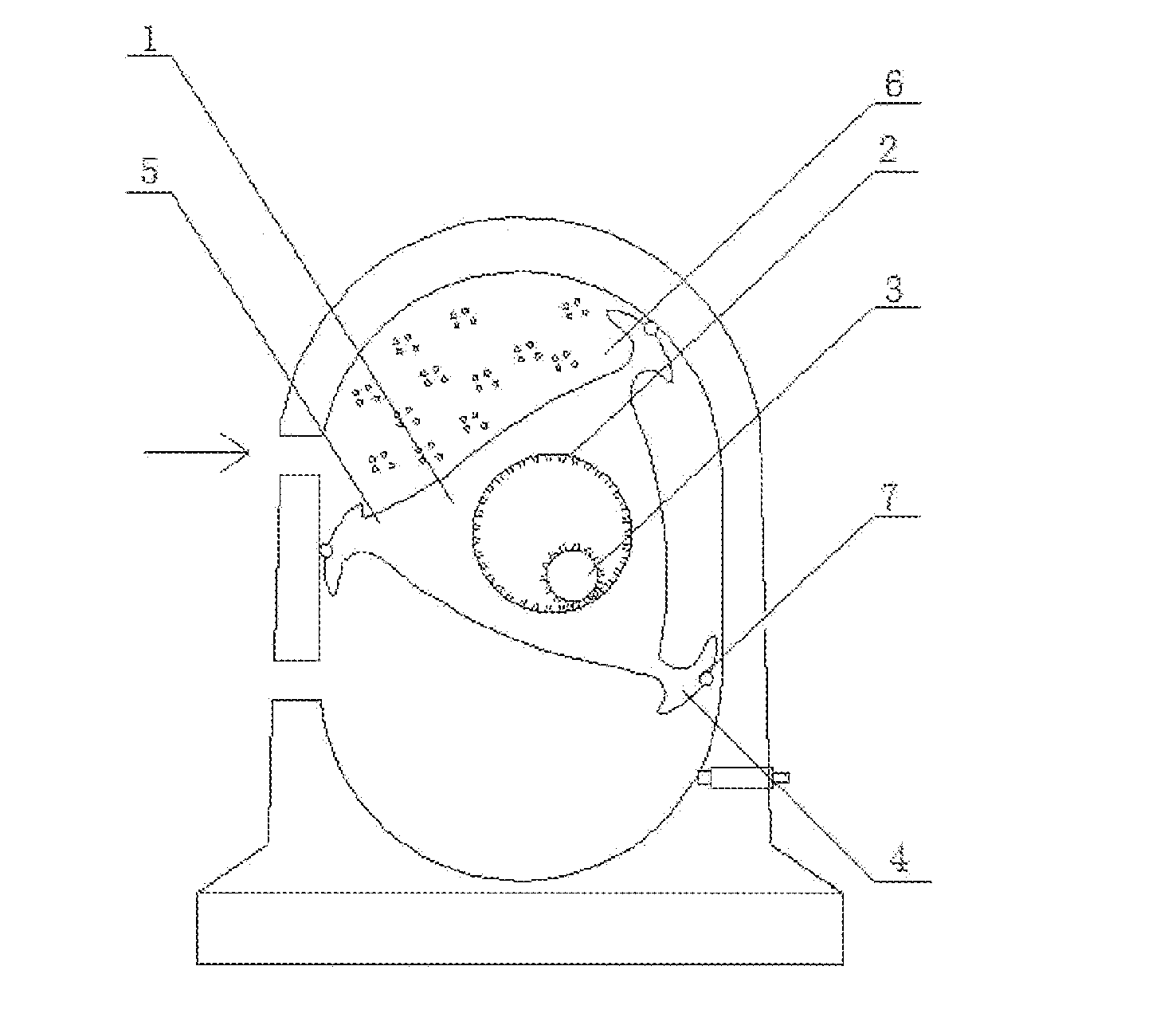
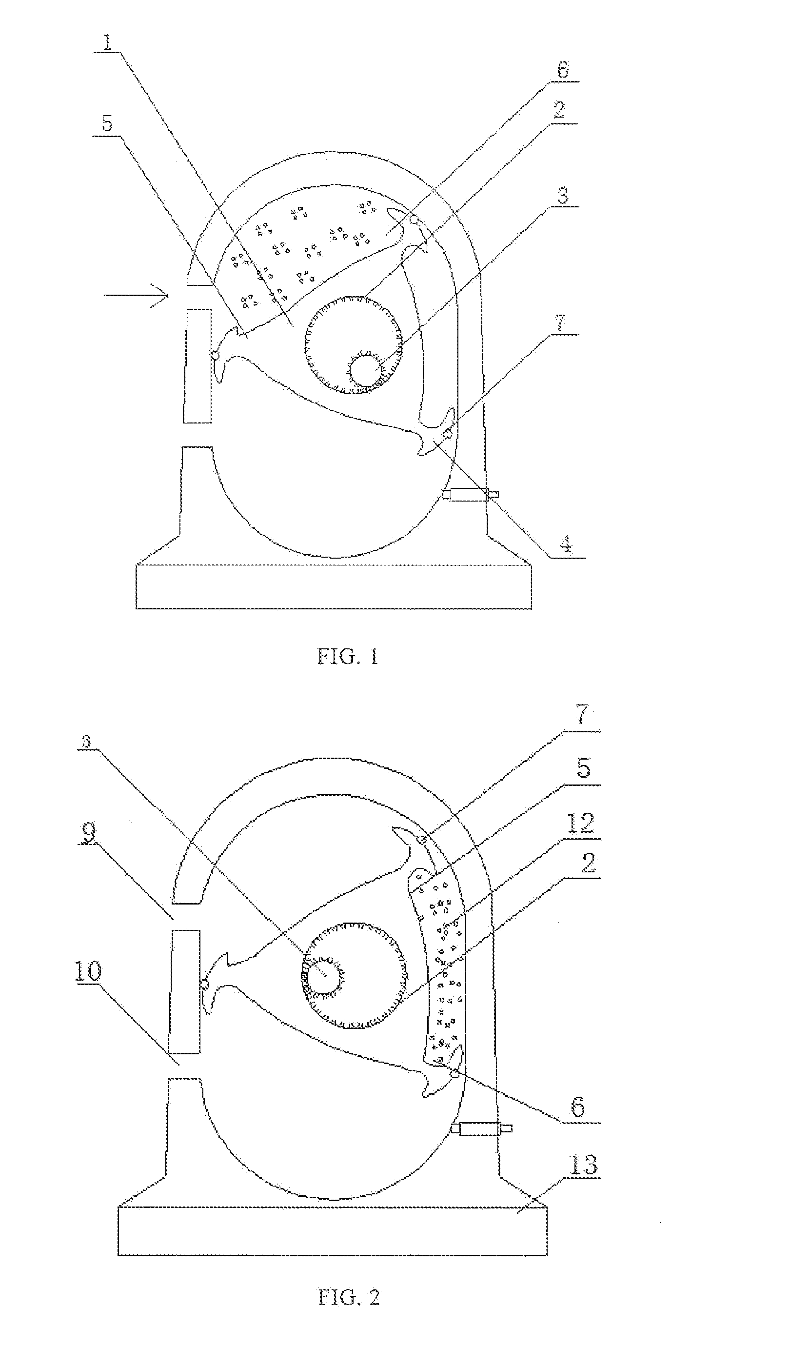
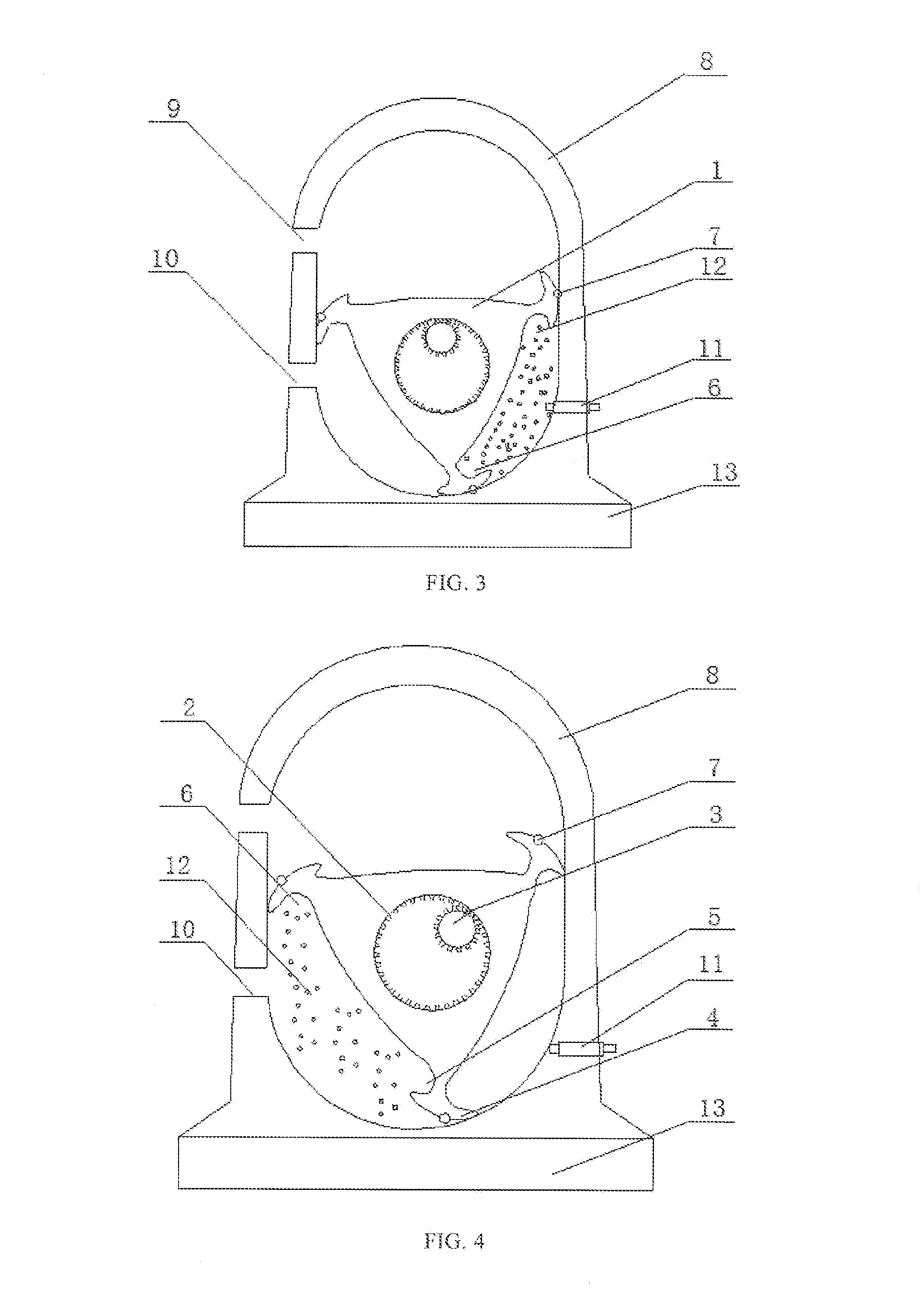
[0031]According to some embodiments of the present disclosure, and referring to FIGS. 1-4, a rotary piston comprises a piston body 1 having a triangular vertical cross-section, mutually engaged large and small planetary gears 2 fixed at the middle of the piston body 1, and a crankshaft 3 running through the small planetary gear. The piston body 1 features three angles on its vertical cross-section, each extending outwards to form a protruded end 4, with a 120-degree gap between adjacent protruded ends. Each protruded end 4 comprises a compression groove 5 formed at one side of the protruded end and a ...


PUM


Abstract

The disclosure relates to a rotary piston, a piston engine comprising the rotary piston, and an engine device comprising the piston engine. The rotary piston comprises a piston body having a triangular vertical cross-section, mutually engaged large and small planetary gears fixed at the middle of the piston body, and a crankshaft running through the small planetary gear. The three angles of the triangular cross-section extend outwards to form protruded ends. The two sides of each protruded end form a compression groove and a combustion groove, respectively. The piston engine of the present disclosure comprises a shell, a crankshaft in the shell and two sets of rotary pistons, wherein the crankshaft has two ends and the two sets of rotary pistons are positioned symmetrically at the two ends of the crankshaft and separated by a holder positioned between the two sets of pistons.

Description

CROSS REFERENCE TO RELATED APPLICATION[0001]This application is a U.S. national application under 35 U.S.C. §111(a) claiming priority, under 35 U.S.C. §119, to Chinese Patent Applications Nos. 201410091834.8 and 201410091788.1, both filed on Mar. 13, 2014, the contents of both of which are incorporated by reference herein in their entirety for all purposes.TECHNICAL FIELD[0002]The present disclosure relates to engine technology, in particular to a rotary piston, a rotary piston engine comprising the rotary piston, and an engine device comprising the rotary piston engine.BACKGROUND[0003]Fuel engines of the current technology include reciprocating engines and rotary engines. With a development history of more than a hundred years, the reciprocating engines have the advantages of mature technology, safety and reliability, and disadvantages of low efficiency, a conversion rate of less than 50%, loud noise, high carbon emission and serious pollution. Rotary engines have the advantages of...

Claims


Application Information

Patent Timeline
IPC IPC(8): F02B53/02F02B53/10
CPCF02B53/10F02B53/02F01C1/22F01C21/08F04C2250/20Y02T10/12
Inventor WANG, WENGE
Owner THREE GEMSTAR AUTOMOTIVE TECH SHANGHAI
Learn More