
Resolver signal processing device, drive apparatus, resolver signal processing method, and program

a technology of resolver signal and signal processing method, which is applied in the direction of dynamo-electric converter control, dynamo-electric gear control, electric generator control, etc., can solve the problem of not easy to extract phase information of phase detected by the resolver

Active Publication Date: 2021-09-02
TOSHIBA MITSUBISHI-ELECTRIC IND SYST CORP
View PDF4 Cites 0 Cited by
  • Summary
  • Abstract
  • Description
  • Claims
  • Application Information

AI Technical Summary

Benefits of technology

The patent text describes a new technology that improves the efficiency of cooling systems for electronic devices. The technology involves a new material that is placed in the cooling system to help transfer heat from the device to a larger area, reducing the risk of overheating and damage to the device. This material can be added to existing cooling systems without needing to entirely replace them, making it easier to improve their performance. The patent text is important for those who work in electronic device design and maintenance.

Problems solved by technology

However, it is not easy to extract phase information of a phase detected by a resolver through a simple method because there is a case in which an output signal of the resolver includes noise, and the like.

Method used


Image

  • Resolver signal processing device, drive apparatus, resolver signal processing method, and program
  • Resolver signal processing device, drive apparatus, resolver signal processing method, and program
  • Resolver signal processing device, drive apparatus, resolver signal processing method, and program

Examples


first embodiment

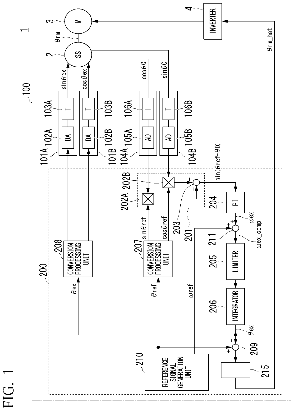
[0016]FIG. 1 is a diagram illustrating a configuration of a drive apparatus 1 including a resolver signal processing device 100 according to an embodiment.

[0017]The drive apparatus 1 includes, for example, a resolver 2 (denoted by SS in the figure), a motor 3 (denoted by M in the figure), an inverter 4, and a resolver signal processing device 100.

[0018]The shaft of the resolver 2 is connected to the output shaft of the motor 3 and rotates in a manner of being linked with rotation of the output shaft of the motor 3. For example, the motor 3 is driven by the inverter 4.

[0019]The resolver signal processing device 100 is connected to the resolver 2, supplies a two-phase excitation signal to the resolver 2 and receives a two-phase signal output from the resolver 2.

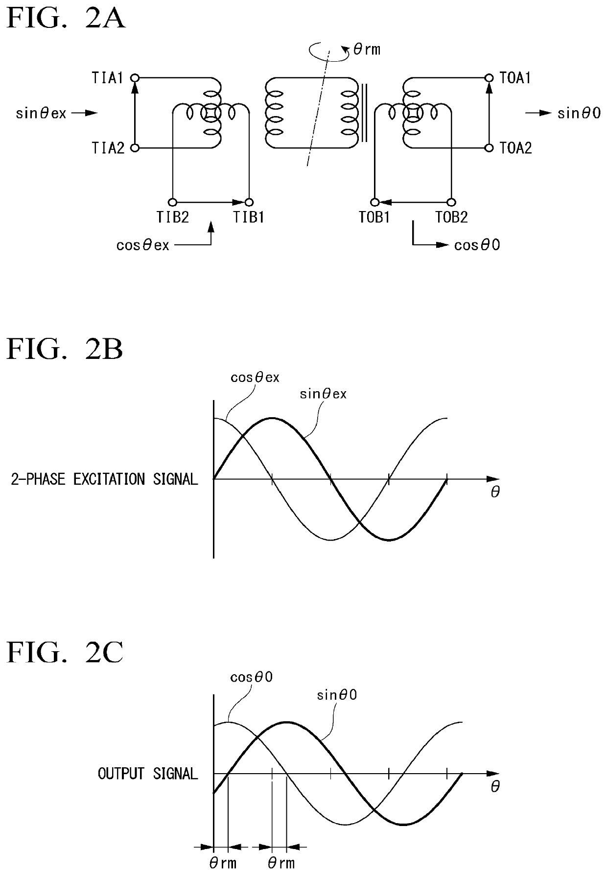
[0020]Here, the resolver 2 will be described with reference to FIG. 2A to FIG. 2C.

[0021]FIG. 2A is a diagram illustrating a configuration of the resolver 2 of an embodiment. FIG. 2B is a diagram for describing a two-phase excit...


PUM


Abstract

A resolver signal processing device includes a deviation calculation unit, a PI operation unit, and an integration operation unit. The deviation calculation unit calculates a deviation between a first product obtained by multiplying a signal of phase A by a cosine value based on a reference phase θref and a second product obtained by multiplying a signal of phase B by a sine value based on the reference phase θref. The PI operation unit carries out a proportional integration operation which includes a first integration operation and is defined to converge the deviation on zero on the basis of the deviation. The integration operation unit carries out a second integration operation of integrating a value generated from a result of the proportional integration operation and outputs a result of the second integration operation as phase information of the resolver.

Description

TECHNICAL FIELD[0001]Embodiments of the present invention relate to a resolver signal processing device, a drive apparatus, a resolver signal processing method, and a program.BACKGROUND ART[0002]A resolver signal processing device extracts phase information of a phase detected by a resolver on the basis of an output signal of the resolver. However, it is not easy to extract phase information of a phase detected by a resolver through a simple method because there is a case in which an output signal of the resolver includes noise, and the like.CITATION LISTPatent Literature[Patent Literature 1][0003]Japanese Unexamined Patent Application, First Publication No. 2016-90244SUMMARY OF INVENTIONTechnical Problem[0004]An object of the present invention is to provide a resolver signal processing device which extracts phase information of a resolver from an output signal of the resolver through a simple method, a drive apparatus, a resolver signal processing method, and a program.Solution to ...

Claims


Application Information

Patent Timeline
Patent Type & Authority Applications(United States)
IPC IPC(8): G01D5/244H02P21/18G01D1/04
CPCG01D5/244G01D1/04H02P21/18G01D5/2073G01D3/036
Inventor MORITO, CHIKARASHIRAISHI, HAJIME
Owner TOSHIBA MITSUBISHI-ELECTRIC IND SYST CORP
Learn More