Electrical connection system comprising a primary connection device and a secondary connection device

a connection system and secondary connection technology, applied in the direction of coupling device connection, localised screening, printed circuit aspects, etc., can solve the problems of large manufacturing tolerance of shielded elements, high cost and complexity of rigid ribbons, and difficult to achieve ground continuity between the two circuit cards. , to achieve the effect of simple structure, low cost and robustness

Active Publication Date: 2021-09-09
SAGEMCOM BROADBAND
View PDF0 Cites 2 Cited by
  • Summary
  • Abstract
  • Description
  • Claims
  • Application Information

AI Technical Summary

Benefits of technology

[0008]An object of the invention is to provide an electrical connection system that is compact, inexpensive, robust, and effective in providing ground continuity in reliable and repeatable manner.SUMMARY OF THE INVENTION
[0010]The electrical connection system of the invention is compact. No wear phenomenon is observed. By means of the shielded cover and the compliant conductive material that is compressed by the shielded cover, total shielding is obtained that is very reliable and without ground discontinuity. Making contact by compression serves to obtain shielding that is very effective regardless of the manufacturing tolerances for the various elements making up the electrical connection system.

Problems solved by technology

In the electrical connection system, ground continuity between the two circuit cards is difficult to achieve in a manner that is reliable and repeatable.
By way of example, internal components and external electrical equipment may include radio receivers that are thus situated inside or outside the equipment in question and that might be disturbed by interference signals generated by fast signals transiting between the two circuit cards.
Such a rigid ribbon is expensive and complicated to use industrially.
There also exist major constraints on the tolerance for manufacturing the shielded elements, since they need to be sufficiently compliant to enable the primary shielding device 5 to be inserted easily while simultaneously ensuring contact that is sufficient.
Furthermore, continuity of contact is generally provided poorly or not at all in corner zones of the primary shielding device 5 and of the secondary shielding device 6.
Finally, a potentially problematic wear phenomenon is frequently observed to occur at the interface between the primary shielding device 5 and the secondary shielding device 6.

Method used


Image

  • Electrical connection system comprising a primary connection device and a secondary connection device
  • Electrical connection system comprising a primary connection device and a secondary connection device
  • Electrical connection system comprising a primary connection device and a secondary connection device

Examples


Embodiment Construction

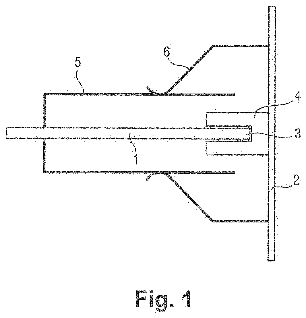
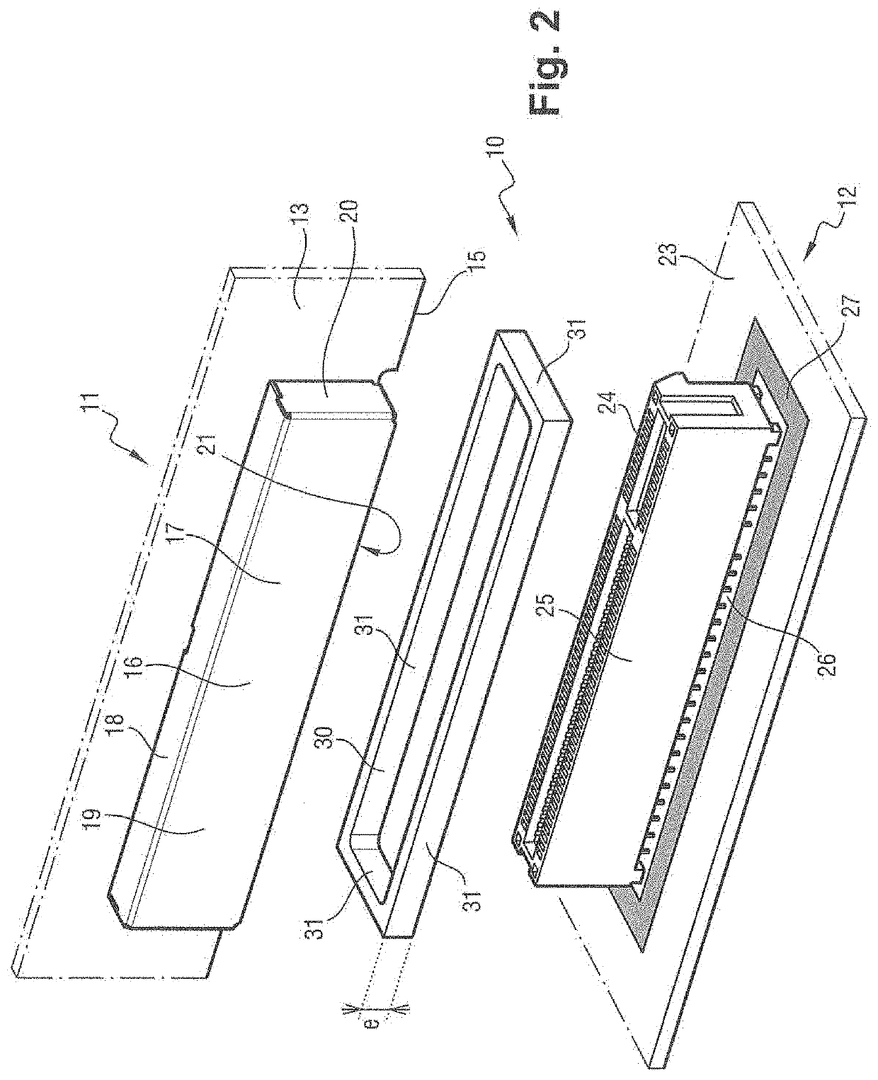
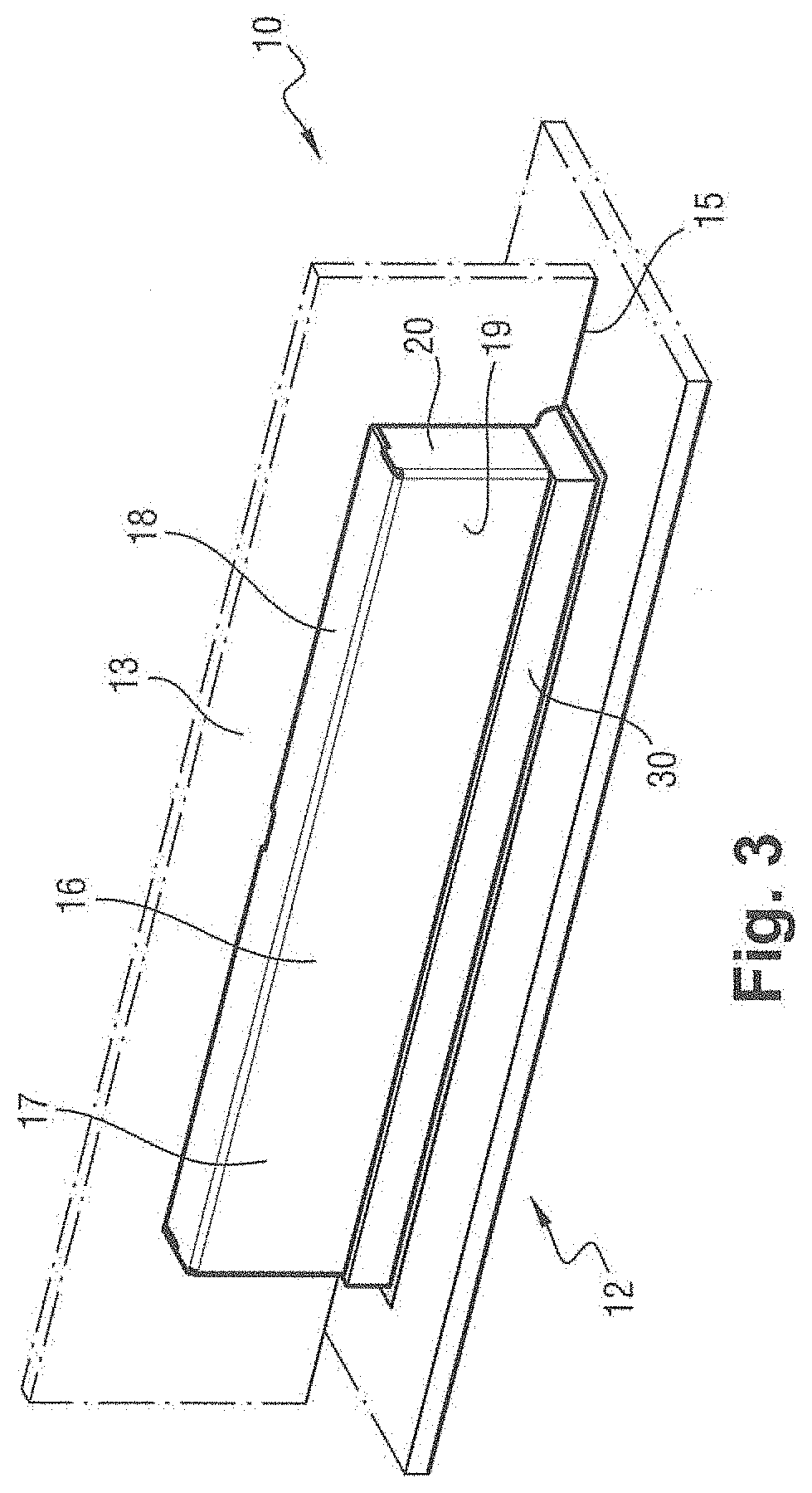
[0022]With reference to FIGS. 2 to 5, the electrical connection system 10 of the invention comprises a primary connection device 11 and a secondary connection device 12.

[0023]The primary connection device 11 is connected to a primary circuit. The secondary connection device 12 is connected to a secondary circuit.

[0024]The primary connection device 11 and the secondary connection device 12 are arranged to be connected together in releasable manner so as to enable the primary circuit and the secondary circuit to be connected together. The primary circuit and the secondary circuit can thus exchange signals (power, data, etc.) via the electrical connection system 10.

[0025]The primary circuit, the secondary circuit, and the electrical connection system 10 are to be incorporated in a single piece of electrical equipment, the primary connection device 11 and the secondary connection device 12 then being connected together.

[0026]The primary connection device 11 firstly comprises a primary e...


PUM

PropertyMeasurementUnit
frequencyaaaaaaaaaa
thicknessaaaaaaaaaa
compression ratioaaaaaaaaaa

Abstract

Electrical connection system comprising a primary connection device and a secondary connection device, the primary connection device comprising a shielded cap and primary conductive contacts which extend at least partially inside the shielded cap, the secondary connection device comprising a secondary electrical board which has a secondary mass surface, secondary conductive contacts which extend from an installation surface of the secondary electrical board which is surrounded by the secondary mass surface, and a resilient conductive material which is attached to the secondary mass surface, the electrical connection system being arranged so that the primary conductive contacts are electrically connected to the secondary electrical contacts inside the shielded cap and the shielded cap extends on the resilient conductive material by compressing it.

Description

[0001]The invention relates to the field of electrical connection systems comprising a primary connection device and a secondary connection device.BACKGROUND OF THE INVENTION[0002]Electrical equipment is frequently designed to comprise two electric circuit cards that are plugged together in releasable manner via an electrical connection system. In the electrical connection system, ground continuity between the two circuit cards is difficult to achieve in a manner that is reliable and repeatable.[0003]It is appropriate to ensure that signals transmitted through the electrical connection system, and in particular signals that are fast, do not disturb the operation of components internal to the electrical equipment that incorporates the electrical connection system, or indeed components of external electrical equipment. By way of example, internal components and external electrical equipment may include radio receivers that are thus situated inside or outside the equipment in question ...

Claims


Application Information

Patent Timeline
Patent Type & Authority Applications(United States)
IPC IPC(8): H01R13/6584H01R12/73H01R12/89
CPCH01R13/6584H05K3/366H01R12/89H01R12/737H05K1/117H01R13/6599H05K9/002H05K2201/10189
Inventor SAHEB, NASSIMLIEVEN, HERVÉLE HENANFF, YANN
Owner SAGEMCOM BROADBAND
Why Eureka
Try Eureka