Automatic constant-temperature dehumidification device

a constant temperature dehumidification and automatic technology, applied in the field of drying equipment, can solve the problems of affecting the smell of hot air leakage, extra operation cost, and affecting the operation efficiency of compression machines, and achieve the effects of shortening the drying cycle, preventing the dust of sludge from drying, and shortening the sludg

Active Publication Date: 2021-09-16
GUANGZHOU SHINCCI ENERGY EQUIP CO LTD
View PDF0 Cites 0 Cited by
  • Summary
  • Abstract
  • Description
  • Claims
  • Application Information

AI Technical Summary

Benefits of technology

[0020]The present invention has the following beneficial effects compared with the prior arts: The present invention has self-balance temperature control, and does not require external air or other cooling sources for cooling. By means of direct discharge to the external environment (cooling), a sealed drying process can be achieved, and there is no leakage of bad smells during the sludge drying process, and therefore it is not necessary to provide a deodorizing device. By separating circulation air volume and dehumidification air volume, the circulation air volume when separated from dehumidification air volume meets the requirements for high air volume in the early stage of wet sludge drying. The dehumidification air volume meets the requirements for high temperature and low humidity in the later stage of sludge drying. Such configurations to meet the air volume, air temperature and humidity requirements in different drying stages of sludge can shorten the sludge, drying cycle and prevent dried dust of sludge.

Problems solved by technology

1. Extra operation cost due to the need of cooling by means of external air or water-cooling by means f a surface cooler to, achieve temperature adjustment during the drying process.
2. Leakage of hot air and also bad smells that affect the peripheral environment if cooling is achieved by external air.
3. Failure to meet different requirements for air volume at different drying, stages during the drying process of the sludge.
4. Failure to meet different requirements for temperature and humidity at different drying stages during the drying process of the sludge.
5. Failure to meet the requirements for a modular structure due to occupation of large surface area and also a large space required for maintenance.

Method used


Image

  • Automatic constant-temperature dehumidification device
  • Automatic constant-temperature dehumidification device
  • Automatic constant-temperature dehumidification device

Examples


embodiment 1

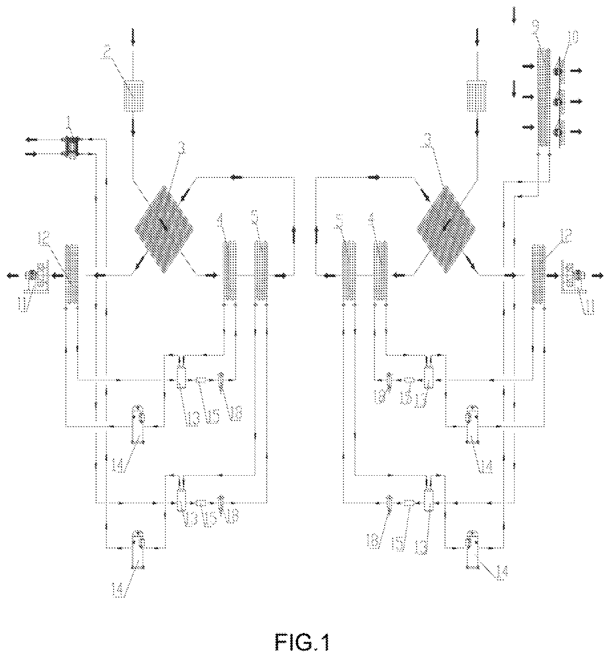
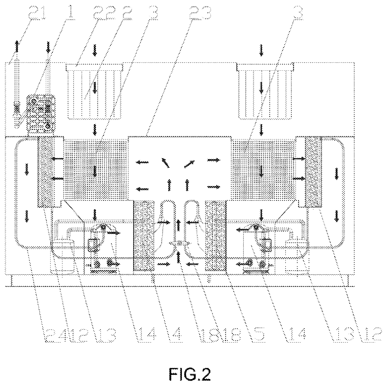
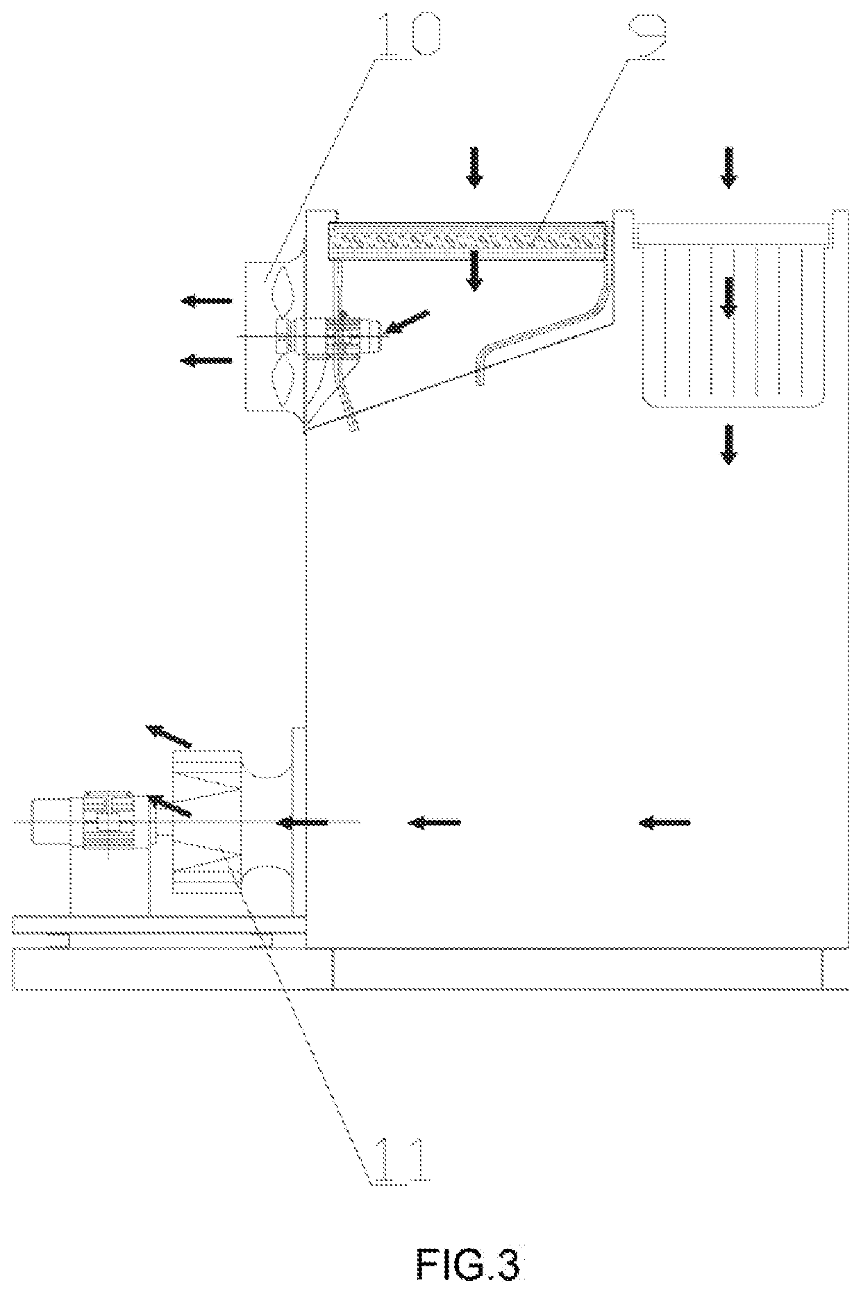
[0027]As shown in FIGS. 1-3, the automatic constant-temperature dehumidification device comprises at least two sets of dehumidifying heat pump assemblies; the two sets of dehumidifying heat pump assemblies comprise two refrigerant modules (a first refrigerant module and a second refrigerant module) and an air module; the first refrigerant module comprises a primary refrigeration module and a secondary refrigeration module; the primary refrigeration module comprises a water condenser 1, a primary evaporator 5, and a compressor 14; an outlet of the compressor 14 is connected to an inlet of the water condenser 1, and an outlet of the water condenser 1 is connected to an inlet of the primary evaporator 5 via an expansion valve 18; an outlet of the primary evaporator 5 is connected to the compressor 14; the secondary refrigeration module comprises a secondary condenser 12, a secondary evaporator 4 and also a compressor 14; an outlet of the compressor 14 of the secondary refrigeration mod...

embodiment 2

[0043]As shown in FIGS. 4-5, the automatic constant-temperature dehumidification device comprises at least two sets of dehumidifying heat pump assemblies; the two sets of dehumidifying heat pump assemblies comprise two refrigerant modules (a first refrigerant module and a second refrigerant module) and an air module; each of the first refrigerant module and the second refrigerant module comprises a primary refrigeration module and a secondary refrigeration module; the primary refrigeration module comprises an air condenser 19, a primary evaporator 5, and a compressor 14; an outlet of the compressor 14 is connected to an, inlet of the air condenser 19, and an outlet of the air condenser 19 is connected to an inlet of the primary evaporator 5 via an expansion valve 18; an outlet of the primary evaporator 5 is connected to the compressor 14; the secondary refrigeration module comprises a secondary condenser 12, a secondary evaporator 4 and also a compressor 14; an outlet of the compres...


PUM

PropertyMeasurementUnit
temperatureaaaaaaaaaa
thicknessaaaaaaaaaa

Abstract

An automatic constant-temperature dehumidification device, comprising at least two dehumidification heat pump assemblies having two refrigerant modules and an air module. The refrigerant module comprises a primary refrigerating module and a secondary refrigerating module, the primary refrigerating module and the secondary refrigerating module each comprising a condenser, an evaporator and a compressor. An air inlet pipe of the air module is connected to a hot side of a heat regenerator, the hot side of the heat regenerator is connected to the evaporators through ventilation pipes, the evaporators are connected to a cold side of the heat regenerator through ventilation pipes, and the cold side of the heat regenerator is connected to one of the condensers through a ventilation pipe.

Description

BACKGROUND OF THE INVENTION[0001]The present invention relates to the technical field of drying apparatus, and more specifically relates to an automatic constant-temperature dehumidification device.[0002]Nowadays, a commonly used drying system for sludge is operated mainly by means of a rotating drum that achieves direct drying, multiple platforms, a rotating disc or a fluidized bed. Yet, belt drying has now received greater attention and has a very good potential for growth in the market due to its strong adaptability to wet sludge, lesser parts that have to be maintained, longer service life and lower drying temperature. Belt drying of sludge that makes use of heat pump dehumidification together with mesh belt sludge drying has become a new trend in the market due to its great advantages on energy conservation and environmental friendliness etc. Heat pump dehumidification in sludge drying technology is going to dominate belt drying of sludge.[0003]A current heat pump for drying an...

Claims


Application Information

Patent Timeline
Patent Type & Authority Applications(United States)
IPC IPC(8): C02F11/13F25B30/02F25B6/02F25B39/04F25B43/00F26B21/00F26B25/06
CPCC02F11/13F25B30/02F25B6/02F25B39/04C02F11/123F26B21/001F26B21/003F26B25/06F25B43/003F25B2400/06F25B2339/047C02F2209/02F26B2200/18F26B21/04F26B21/086C02F11/12F26B21/12F26B23/005Y02B30/52Y02P70/10
Inventor SHI, ZENGKUANG
Owner GUANGZHOU SHINCCI ENERGY EQUIP CO LTD
Why Eureka
Try Eureka