Diagnostic device, diagnostic method, and program
a technology of diagnostic devices and diagnostic methods, applied in the direction of electric devices, battery/fuel cell control arrangements, instruments, etc., can solve the problem of reducing the charge state, and achieve the effect of reducing the degree of deterioration of secondary batteries, high accuracy, and high accuracy
- Summary
- Abstract
- Description
- Claims
- Application Information
AI Technical Summary
Benefits of technology
Problems solved by technology
Method used
Image
Examples
first embodiment
[0046][Entire Configuration]
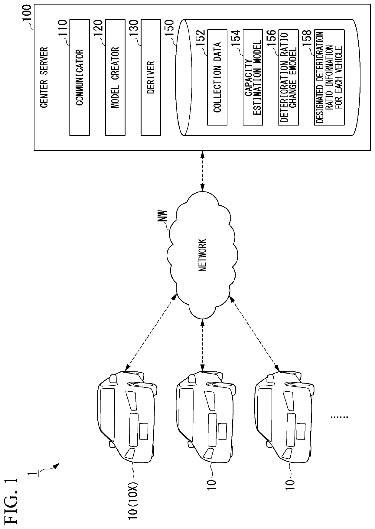
[0047]FIG. 1 is a diagram showing an example of a configuration of a diagnostic system 1 according to a first embodiment. The diagnostic system 1 is a battery deterioration diagnosis system that diagnoses deterioration of a battery (hereinafter, which is synonymous with a secondary battery) which is mounted in a vehicle 10. As shown in FIG. 1, the diagnostic system 1 includes a plurality of vehicles 10 and a center server (a diagnostic device) 100. In the following description, a vehicle 10 which transmits battery use status information and in which a designated deterioration ratio arrival time is displayed out of the plurality of vehicles 10 is defined as an target vehicle 10X.
[0048]The center server 100 diagnoses the batteries mounted in a plurality of vehicles 10 on the basis of information transmitted from the plurality of vehicles 10. The vehicles 10 and the center server 100 communicate with each other via a network NW. The network NW includes, for ...
second embodiment
[0097]A second embodiment will be described below. FIG. 10 is a diagram showing an example of a configuration of a vehicle 10A according to the second embodiment. The configuration according to the second embodiment is different from the configuration according to the first embodiment, in that an element having the same function as the deriver 130 provided in the center server 100 is provided as a derivation device 55 in the vehicle 10A. The configuration according to the second embodiment is almost the same as the configuration according to the first embodiment in the other points. Processes in the second embodiment will be described below with a focus on differences from the first embodiment.
[0098]The derivation device 55 includes a deriver having the same configuration as the deriver 130 of the first embodiment and a storage having the same configuration as the storage 150. The storage of the derivation device 55 stores a designated deterioration ratio in the vehicle 10A. In the ...
third embodiment
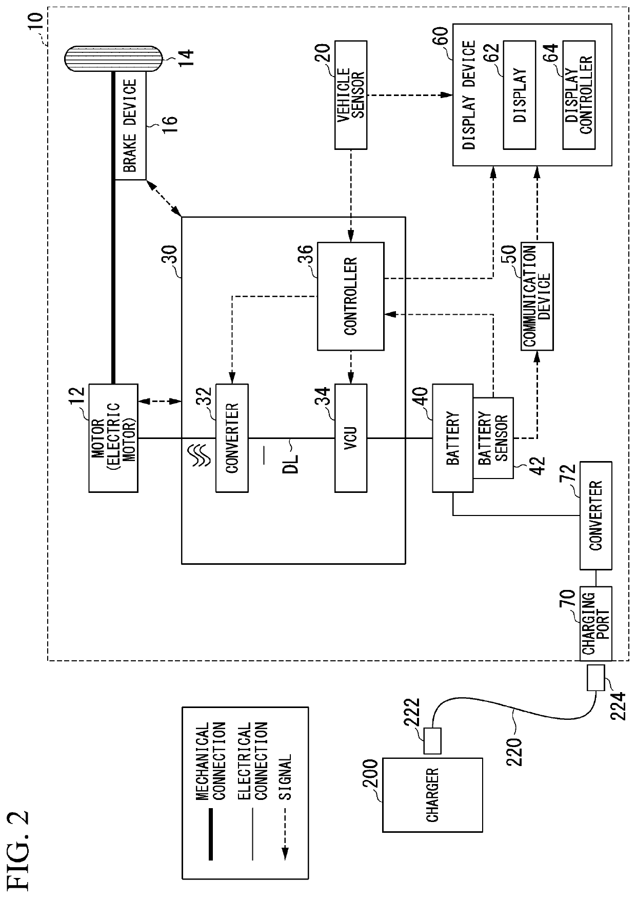
[0101]A third embodiment will be described below. FIG. 11 is a diagram showing an example of a configuration of a vehicle 10B according to the third embodiment. The configuration according to the third embodiment is different from the configuration according to the first embodiment, in that an adjustment and display device 80 shown in FIG. 11 is provided instead of the display device 60 shown in FIG. 1. The display device 60 according to the first embodiment displays a lifespan of a battery 40 as a future state, but the adjustment and display device 80 according to the third embodiment also displays a residual value of the battery 40 as a future state. The configuration according to the third embodiment is almost the same as the configuration according to the first embodiment in the other points. The third embodiment will be described below with a focus on differences from the first embodiment.
[0102]As shown in FIG. 11, a vehicle 10B includes an adjustment and display device 80. The...
PUM
 Abstract
Description
Claims
Application Information
 - R&D
- Intellectual Property
- Life Sciences
- Materials
- Tech Scout
- Unparalleled Data Quality
- Higher Quality Content
- 60% Fewer Hallucinations
Browse by: Latest US Patents, China's latest patents, Technical Efficacy Thesaurus, Application Domain, Technology Topic, Popular Technical Reports.
© 2025 PatSnap. All rights reserved.Legal|Privacy policy|Modern Slavery Act Transparency Statement|Sitemap|About US| Contact US: help@patsnap.com


