
Split-type nut assembly

a nut and split-type technology, applied in the direction of belts/chains/gearrings, mechanical equipment, belts/chains/gearrings, etc., can solve the problems of increasing errors, users having to take a long time to disassemble the whole mechanism, and users cannot easily disassemble these nuts, etc., to achieve easy assembly and disassembly, and the effect of reducing the effect of clearance elimination

Inactive Publication Date: 2021-09-23
SHANGHAI MOONS ELECTRICAL APPLIANCE
View PDF0 Cites 0 Cited by
  • Summary
  • Abstract
  • Description
  • Claims
  • Application Information

AI Technical Summary

Benefits of technology

The invention relates to a split-type nut assembly with a long-lasting clearance elimination effect. The two nuts are engaged in the threaded shaft under the effect of the connector, and they become more and more tightly in the joint direction with wear agavation, reducing the clearance elimination effect. The split-type nut assembly can bear a load over 50N without generating an obvious clearance, and it is easy to assemble and disassemble by users. The technical effects of the invention include a long-lasting clearance elimination effect, high load bearing capacity, easy assembly and disassemble, and reduced costs.

Problems solved by technology

Due to the fact that nuts may become worn after being used for a period of time and that a clearance generated after the nuts are worn may result in positional errors when the motion direction of the nuts is changed, the primary issue that should be taken into consideration for improving the precision of screw pairs is how to eliminate these motion errors.
However, such a solution has the drawback that when the nuts bear a large load, a reactive force will be applied to the axial spring and an anti-backlash system moves reversely, which in turn increase the errors.
However, after users assemble a whole screw pair on a machine or a mechanism, the end of the threaded shaft has usually already been connected to other mechanisms with a bearing or other components, and in this case, if the nuts break down after long-time operation, the users cannot easily disassemble these nuts, or the users have to take a long time to disassemble the whole mechanism connected with the screw pair and then to repair these broken nuts or to replace these broken nuts with new ones.
However, due to the fact that a torsion spring is used for connecting two nuts to eliminate a clearance, the torsion spring-based anti-backlash nut is inapplicable on large-load occasions and is difficult to disassemble.

Method used


Image

  • Split-type nut assembly
  • Split-type nut assembly
  • Split-type nut assembly

Examples


Embodiment Construction

[0040]Technical solutions of embodiments of the invention are clearly and completely explained below in combination with the accompanying drawings. Apparently, the embodiments in the following description are only certain illustrative ones and not all possible ones of the invention. All other embodiments obtained by those ordinarily skilled in this field based on these illustrative ones without creative work should also fall within the protection scope of the invention.

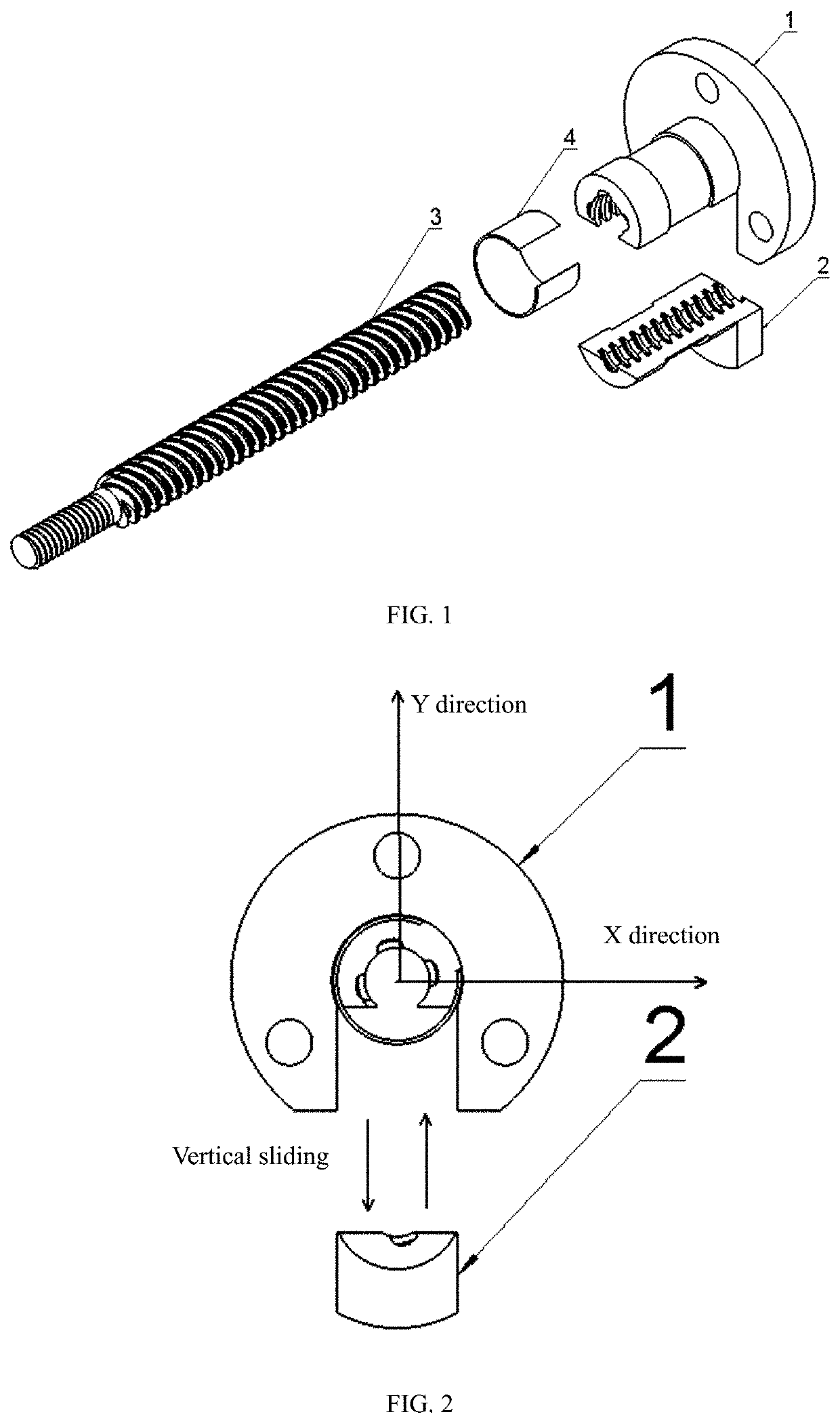
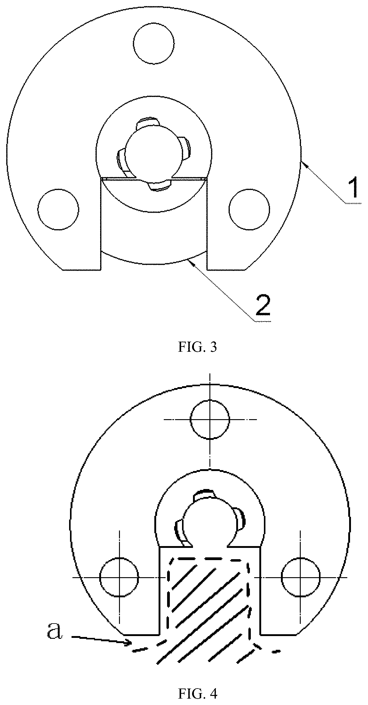
[0041]As shown in FIG. 1 and FIG. 3, a split-type nut assembly comprises a first nut 1 and a second nut 2 which are completely separated from each other. The first nut 1 and the second nut 2 have identical pitches and leads and are matched with each other or move relative to each other on a threaded shaft 3.

[0042]The split-type nut assembly further comprises a connector 4, wherein the first nut 1 and the second nut 2 are connected in a semi-floating manner through the connector 4.

[0043]The connector 4 is an elastic el...


PUM


Abstract

The invention relates to a split-type nut assembly. The split-type nut assembly comprises a first nut and a second nut which are completely separated from each other. The first nut and the second nut have identical pitches and leads and are matched with each other or move relative to each other on a threaded shaft. Compared with the prior art, the split-type nut assembly has the advantages of being good in clearance elimination effect, long in service life, convenient to disassemble and the like.

Description

TECHNICAL FIELD[0001]The invention relates to the field of motor structures, in particular to a split-type nut assembly.DESCRIPTION OF RELATED ART[0002]Micro lead screws and micro nuts have been widely used in the motion control field. Due to the fact that nuts may become worn after being used for a period of time and that a clearance generated after the nuts are worn may result in positional errors when the motion direction of the nuts is changed, the primary issue that should be taken into consideration for improving the precision of screw pairs is how to eliminate these motion errors.[0003]According to existing techniques, a spring through which two nuts having identical leads are connected in the axial direction is used to provide an axial pushing or pulling force for the nuts to overcome a load and to eliminate a clearance. However, such a solution has the drawback that when the nuts bear a large load, a reactive force will be applied to the axial spring and an anti-backlash sy...

Claims


Application Information

Patent Timeline
Patent Type & Authority Applications(United States)
IPC IPC(8): F16H25/20F16H25/24
CPCF16H25/2009F16H25/24F16H25/2006
Inventor ZENG, KAIWU, ZHIGANGUO, YANMENGYUAN, WUFENGLIU, GUANGYU
Owner SHANGHAI MOONS ELECTRICAL APPLIANCE
Learn More