
Apparatus And Method Of Eliminating Settling Time Delays In A Radar System

a radar system and time delay technology, applied in the field of radar imaging, sonar, ultrasound, can solve the problems of reduced cost of associated technology, poor visibility, degraded visual sensors, etc., and achieve the effect of removing time delays

Pending Publication Date: 2021-09-23
ARBE ROBOTICS LTD
View PDF0 Cites 11 Cited by
  • Summary
  • Abstract
  • Description
  • Claims
  • Application Information

AI Technical Summary

Benefits of technology

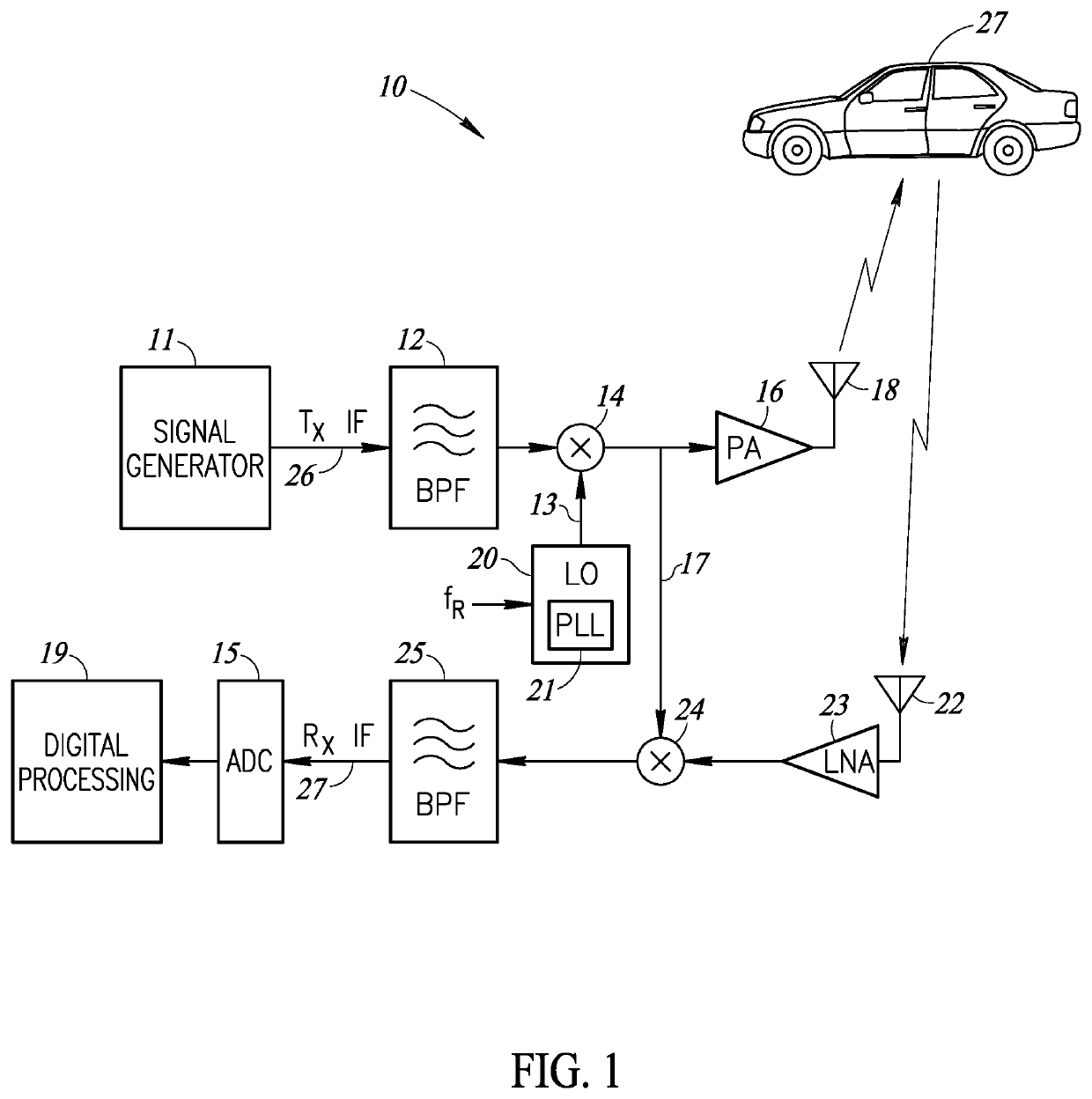
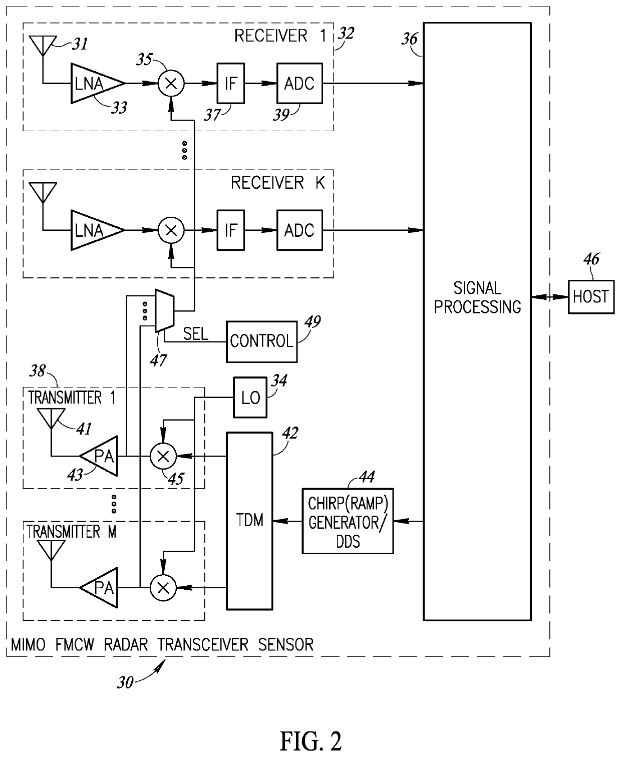
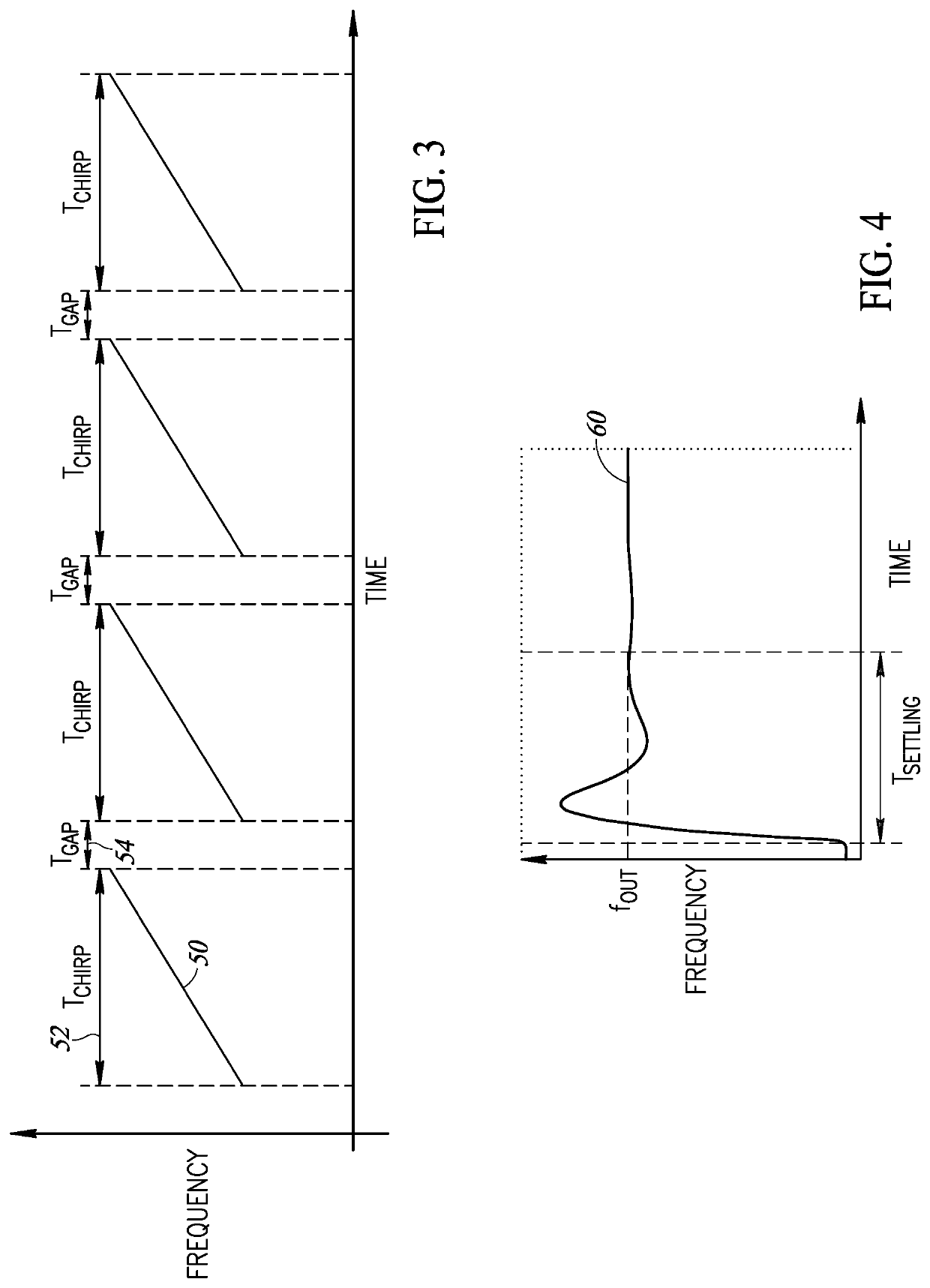
The present invention is a system and method for reducing delays in a radar system. It uses multiple oscillators or transmitters, which allows for faster startup and reduced settling time between chirp transmissions. This results in improved radar performance and efficiency. In one embodiment, a single transmitter is used with multiple oscillators, while in another embodiment, each transmitter has its own oscillator. This technology works for various sensors such as imaging radar and sonar.

Problems solved by technology

Besides cameras and ultrasonic sensors, car makers are turning to radar as the cost of the associated technology decreases.
Visual sensors are also degraded by bad weather and poor visibility (e.g., fog, smoke, sand, rain or snow storms, etc.).
They are also limited in estimating radial velocities.
These, however, are expensive, as most have moving parts and very limited range.
The reception of foreign signals (interference) can lead to problems such as ghost targets or a reduced signal-to-noise ratio.
On the contrary, safety functions of future systems require very low failure rates.
Therefore, radar-to-radar interference is a major problem in radar sensor networks, especially when several radars are concurrently operating in the same frequency band and mutually interfering with each another.
As stated supra, a major challenge facing the application of automotive radar to autonomous driving is the highly likely situation where several unsynchronized radars, possibly from different vendors, operate in geographical proximity and utilize overlapping frequency bands.
Note that the currently installed base of radars cannot be expected to synchronize with new automotive radar sensor entrants, nor with any global synchronization schemes.

Method used


Image

  • Apparatus And Method Of Eliminating Settling Time Delays In A Radar System
  • Apparatus And Method Of Eliminating Settling Time Delays In A Radar System
  • Apparatus And Method Of Eliminating Settling Time Delays In A Radar System

Examples


Embodiment Construction

[0049]In the following detailed description, numerous specific details are set forth in order to provide a thorough understanding of the invention. It will be understood by those skilled in the art, however, that the present invention may be practiced without these specific details. In other instances, well-known methods, procedures, and components have not been described in detail so as not to obscure the present invention.

[0050]Among those benefits and improvements that have been disclosed, other objects and advantages of this invention will become apparent from the following description taken in conjunction with the accompanying figures. Detailed embodiments of the present invention are disclosed herein; however, it is to be understood that the disclosed embodiments are merely illustrative of the invention that may be embodied in various forms. In addition, each of the examples given in connection with the various embodiments of the invention which are intended to be illustrative...


PUM


Abstract

A novel and useful system and method for eliminating settling time delays in a radar system. In one embodiment, a plurality of oscillators is provided with a single transmitter. In an alternative embodiment, a plurality of transmitters is provided, each with its own oscillator. In either case, more than a single oscillator is used, whereby startup or turn on transients associated with one oscillator are allowed to settle out while another oscillator is being used. The two or more oscillators switch off and / or alternate or rotate such that oscillator settling time between chirp transmissions from the radar is substantially or completely eliminated. In a radar system having two transmitters, when the chirp propagation time window for the first transmitter is complete, the first transmitter is disconnected from the receive channel and the second transmitter is connected to the antenna and receive channel without having to wait for the second transmitter to settle since it was allowed to settle beforehand.

Description

FIELD OF THE DISCLOSURE[0001]The subject matter disclosed herein relates to the field of imaging radar, sonar, ultrasound, and other sensors for performing range measurement via FMCW signals and / or angle measurement via digital beam forming and array processing and more particularly relates to a system and method for eliminating settling time delays in a radar system.BACKGROUND OF THE INVENTION[0002]Recently, applications of radars in the automotive industry have started to emerge. High-end automobiles already have radars that provide parking assistance and lane departure warning to the driver. Currently, there is a growing interest in the self-driving cars and some people consider it to be the main driving force of the automotive industry in the coming years.[0003]Self-driving cars offer a new perspective on the application of the radar technology in automobiles. Instead of only assisting the driver, automotive radars should be capable of taking an active role in the control of the...

Claims


Application Information

Patent Timeline
IPC IPC(8): G01S7/40
CPCG01S7/40G01S13/343G01S7/4017G01S13/931G01S13/42
Inventor ARKIND, NOAMBAUER, ABRAHAM
Owner ARBE ROBOTICS LTD
Learn More