Method And Apparatus For Separation Of A Substance From Water

a technology for separating a substance and a water source, applied in the direction of water/sewage multi-stage treatment, water/sewage treatment by oxidation, water/sewage treatment by multi-stage treatment, etc., can solve the problems of contaminated soils, groundwater and drinking water supplies, and pfas contamination, and achieve the effect of treating groundwater with pfas contamination and not working techniques

Pending Publication Date: 2021-09-30
OPEC REMEDIATION TECH PTY LTD
View PDF3 Cites 3 Cited by
  • Summary
  • Abstract
  • Description
  • Claims
  • Application Information

AI Technical Summary

Benefits of technology

[0014]In a first aspect there is provided a method of separating an amount of a substance from water which is contaminated with the substance, the method comprising the steps of: admitting an amount of the water, which includes an initial concentration of the substance, into a chamber via an inlet thereinto; introducing a flow of gas into the chamber, wherein said introduced gas induces the water in the chamber to flow, and produces a froth layer which is formed at, and which rises above, an interface with the said flow of water and of introduced gas in the chamber, the froth layer including an amount of water and also a concentrated amount of the substance when compared with its initial concentration; controlling the water content of the froth layer which rises above the interface to influence the concentration of the substance therein; and removing at least some of the froth layer from an upper portion of the chamber.

Problems solved by technology

They are recalcitrant, bio-accumulative and known to have contaminated soils, groundwaters and drinking water supplies.
PFAS are known to have contaminated groundwater, including drinking water supplies.
However, it is also known that such techniques do not work to treat groundwater with PFAS contamination.
While they are soluble, most long-chain PFAS (including PFOS and PFOA have a low, to very low, vapour pressure, which means they do not volatilise easily, so air-stripping is therefore not an ineffective remedial treatment.
This technique is costly because of the expense of transporting large quantities of water from place to place.
In general, the treatment agents used in these technologies are either sensitive to fouling by non-compatible substances or cannot be easily regenerated and require disposal (typically to landfill) after they have reached maximum capacity.
There are currently no commercially viable technologies available using chemical approaches that are capable of degrading or destroying many of the key PFAS compounds of concern where they are present in low concentrations in large volumes of water.
Pump and treat systems are usually required to operate for extended periods over many years, and the treatment volumes are very large—as a result, the treatment plant equipment is also large.
Capital and operating costs are typically high due to treatment plant size and long operational time periods (years, or even decades).
However, PFAS are recalcitrant, and laboratory studies have found limited success with performance of these reagents.
Such wells can involve complex, multiple screen sections in side walls, which may need to be separated by packers or low permeability barriers.
It has become apparent that there are no suitable technologies which overcome the cost, scale and risk of the known techniques when applying them to try to neutralise PFAS.
If too much gas is introduced into the chamber, the flow of water can move away from its ideal treatment condition of quiescent flow, and instead become turbulent.
In turbulent situations, the froth layer can become disrupted and can also become very wet and thus cause dilution of the concentration of the substance that is being removed from the water.
However, in turbulent fluid flow situations, stability of the level control provided by a floating device can be more uncertain.
In one form of this, the said device controls the cross-sectional flow path of the froth in the chamber, resulting in froth confinement and drainage.

Method used


Image

  • Method And Apparatus For Separation Of A Substance From Water
  • Method And Apparatus For Separation Of A Substance From Water
  • Method And Apparatus For Separation Of A Substance From Water

Examples


Embodiment Construction

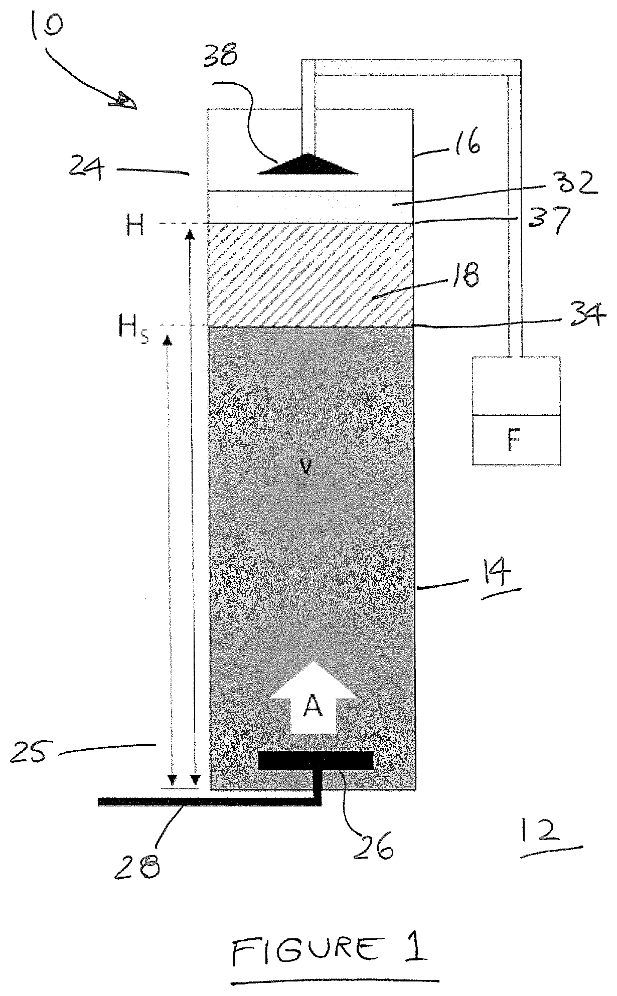
[0122]This disclosure relates to the features of a flotation cell 10 and its use for removal of an organic contaminant from a water supply which is pumped into that cell 10. Typically, such contaminated water has been obtained by extraction pumping from a nearby aquifer or water storage which has a certain level of organic contaminant(s) which have become dissolved or dispersed therein. A small amount of suspended solids may also be present, so that the water may have some turbidity.

[0123]Referring to the embodiment shown in FIG. 1, the flotation cell 10 is in the form of an elongate, cylindrical column 16 having an interior chamber 18. The column 16 is circular in cross-section, and is positioned to stand vertically upright on surrounding ground 12. The column 16 can be a tube or a plurality of casing elements 14 which is made of hard plastic or metal, to be sufficient to withstand the hydraulic pressure of the depths of water it is to contain, and not collapse or corrode.

[0124]The...


PUM

PropertyMeasurementUnit
concentrationaaaaaaaaaa

Abstract

A method and apparatus is disclosed for separating an amount of a perfluoroalkyl or polyfluoroalkyl substance (PFAS) from water which is contaminated with the substance. The method comprises the steps of: admitting an amount of the water, which includes an initial concentration of the substance, into a chamber via an inlet thereinto, and introducing a flow of gas into the chamber. The introduced gas induces the water in the chamber to flow, and produces a froth layer which is formed at, and which rises above, an interface with the said flow of water and of introduced gas in the chamber. The froth layer includes an amount of water, and also a concentrated amount of the substance in comparison compared with its initial concentration. The step of removal of at least some of the froth layer from an upper portion of the chamber occurs.

Description

TECHNICAL FIELD[0001]This disclosure relates to an apparatus for separation of a substance from water and to a method for use of the separation apparatus. In one form, the apparatus and method can be applied to removal of contaminant organic material present in groundwater which has been extracted from a body of ground. However, the apparatus and method can also be applied to the removal of non-organic materials or contaminants from all types of contaminated water sources.BACKGROUND OF THE DISCLOSURE[0002]Perfluoroalkyl or polyfluoroalkyl substances (PFAS) embody a range of poly fluorinated alkyl substances (including but not limited to carboxylic acids, alkyl sulfonates, alkyl sulfonamido compounds and fluoro telemeric compounds of differing carbon chain lengths and precursors of these). PFAS have found use in a wide variety of applications including as a specialised fire-fighting product, or for impregnation or coating of textiles, leather and carpet, or for carpet cleaning compou...

Claims


Application Information

Patent Timeline
Patent Type & Authority Applications(United States)
IPC IPC(8): C02F1/24
CPCC02F1/24C02F2101/36B03D1/24B03D1/028B03D1/1462B03D2203/008C02F2103/06C02F1/283C02F1/42C02F1/74C02F9/00C02F2101/203C02F2101/206C02F2209/05C02F2209/42C02F2301/022C02F2209/38C02F2209/40C02F2301/026C02F2301/08
Inventor PHILLIPS, STEVEN EDWARD
Owner OPEC REMEDIATION TECH PTY LTD
Why Eureka
Try Eureka