Equipment determination method of cogeneration system, equipment determination device thereof, and computer readable recording medium thereof

a technology of equipment determination and cogeneration system, which is applied in the direction of lighting and heating apparatus, heating types, instruments, etc., can solve the problems of reducing not being able to easily repeat stop and start, etc., and achieve the effect of preventing a decrease in the efficiency of an entire system

Active Publication Date: 2021-09-30
YAZAKI ENERGY SYST
View PDF13 Cites 1 Cited by
  • Summary
  • Abstract
  • Description
  • Claims
  • Application Information

AI Technical Summary

Benefits of technology

[0007]Therefore, it is desirable to make good use of waste heat while base-load operating the cogeneration equipment at a full load for 24 hours and 365 days, for example, but the heat must be wasted by a radiator when a heat load for using waste heat is absent. For this reason, a heat storage tank or a hot water storage tank may be provided so as to avoid wasting heat, but efficiency of an entire system is reduced when a capacity is not appropriate for the cogeneration equipment.
[0009]The present invention has been made so as to solve such problems in the related art, and an object of the present invention is to provide an equipment determination method of cogeneration system, an equipment determination device thereof, and a computer readable recording medium thereof capable of preventing a decrease in efficiency of an entire system.
[0011]According to the present invention, it is possible to prevent a decrease in efficiency of an entire system.

Problems solved by technology

Further, some cogeneration equipment have a long start-up time when temporarily stopped, it is not possible to easily repeat stop and start-up, and an operation for 24 hours and 365 days is a standard.
For this reason, a heat storage tank or a hot water storage tank may be provided so as to avoid wasting heat, but efficiency of an entire system is reduced when a capacity is not appropriate for the cogeneration equipment.
Also, this problem is not limited to a cogeneration equipment that performs a base load operation at a full load for 24 hours and 365 days, but is also common to, for example, a cogeneration equipment that cannot be stopped as much as possible or that does not perform a partial load operation as much as possible.
Therefore, this problem is a common problem in a cogeneration equipment which is stopped for a few days out of 365 days, or for a few hours out of 24 hours.

Method used


Image

  • Equipment determination method of cogeneration system, equipment determination device thereof, and computer readable recording medium thereof
  • Equipment determination method of cogeneration system, equipment determination device thereof, and computer readable recording medium thereof
  • Equipment determination method of cogeneration system, equipment determination device thereof, and computer readable recording medium thereof

Examples


Embodiment Construction

[0019]Hereinafter, the present invention will be described according to a preferred embodiment, and a cogeneration system will be described prior to the embodiment.

[0020]The present invention is not limited to the following embodiment, and can be modified as appropriate without departing from the scope of the present invention. Although a part of configurations may not be illustrated or described in the embodiments to be described below, it goes without saying that a known or well-known technique is appropriately applied to details of an omitted technique within a range in which no contradiction occurs to contents to be described below.

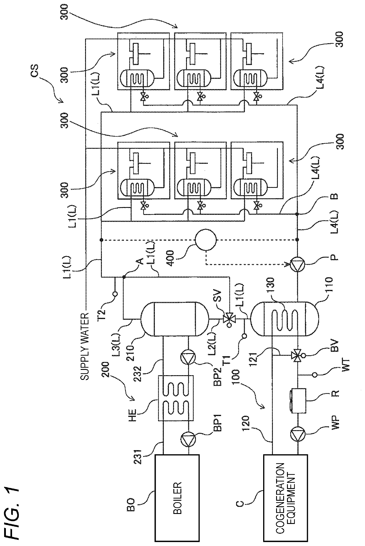
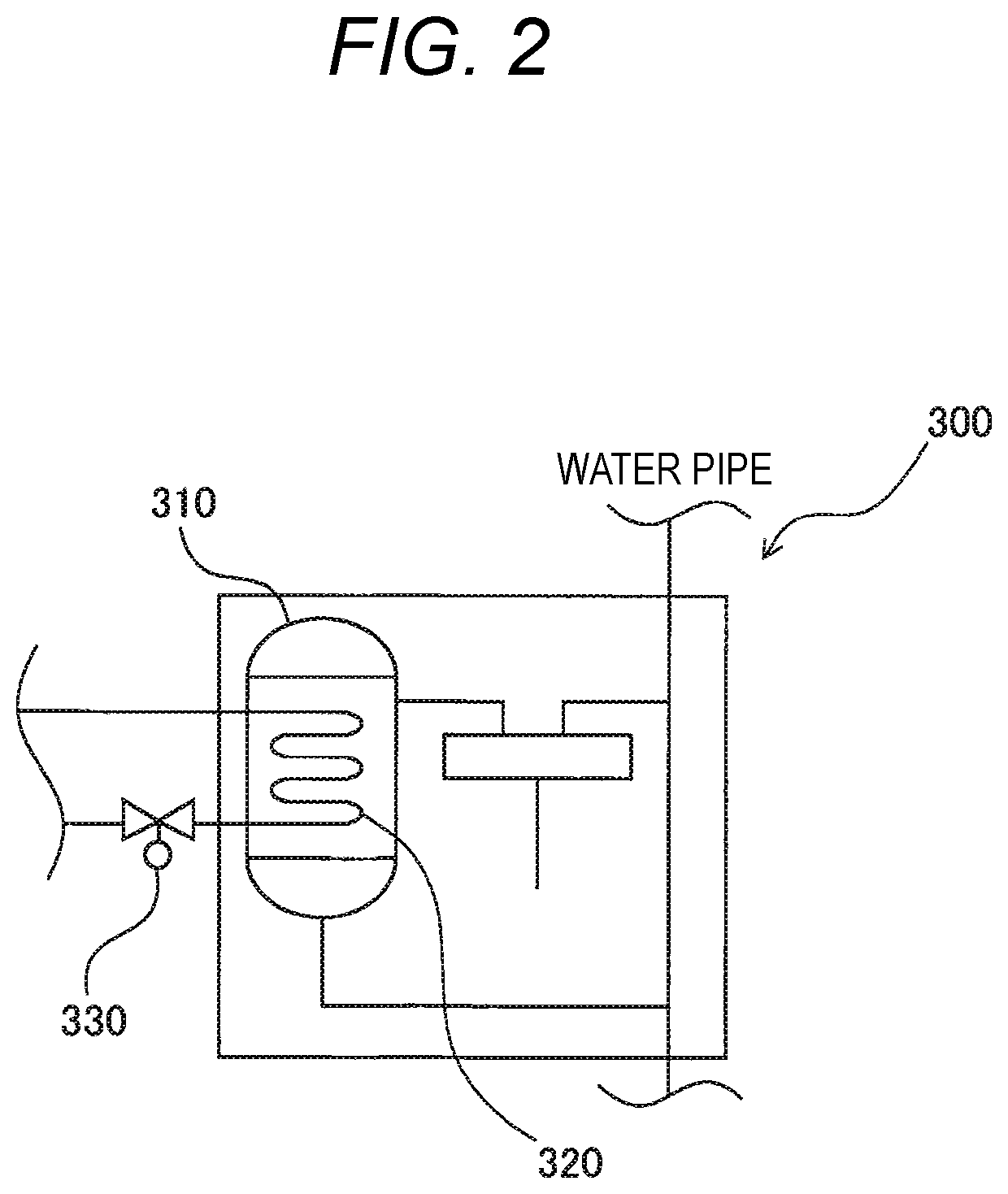
[0021]FIG. 1 is a configuration diagram showing an example of the cogeneration system, and FIG. 2 is a partial configuration diagram of the cogeneration system shown in FIG. 1.

[0022]A cogeneration system CS shown in FIG. 1 includes a first equipment 100 including a cogeneration equipment C, a second equipment 200 including a boiler BO, a plurality of ...


PUM


Abstract

An equipment determination method of a cogeneration system includes the steps of: calculating a total hot water supply load for each day over a predetermined period longer than a specific period based on each unit hot water supply load for hour according to hot water supply use by consumers; setting as a representative period a specific period on which the total hot water supply load becomes at least a low load among the calculated total hot water supply load for each day; determining a capacity of the cogeneration equipment based on the total hot water supply load on the set representative period; and determining a capacity of the plurality of hot water storage tanks based on an amount of hot water supply load exceeding the capacity of the determined cogeneration equipment among each unit hot water supply load for two or more divided periods including the set representative period.

Description

CROSS-REFERENCE TO RELATED APPLICATIONS[0001]This application is based on and claims priority under 35 USC 119 from Japanese Patent Application No. 2020-056958 filed on Mar. 27, 2020, the contents of which are incorporated herein by reference.TECHNICAL FIELD[0002]The present invention relates to an equipment determination method of a cogeneration system, an equipment determination device thereof, and a computer readable recording medium thereof.BACKGROUND ART[0003]In the related art, there has been known a cogeneration system using waste heat of a fuel cell, a gas engine, or the like for hot water supply (see Patent Literature 1). Some of such cogeneration systems are applied to a housing complex, a long-term care facility, a hospital, and the like.CITATION LISTPatent Literature[0004]Patent Literature 1: Japanese Patent No. 4426860SUMMARY OF INVENTION[0005]Here, a cogeneration system used in a housing complex or the like includes a cogeneration equipment that generates electric powe...

Claims


Application Information

Patent Timeline
Patent Type & Authority Applications(United States)
IPC IPC(8): F24D19/10F28D21/00F24D3/08G05B15/02F02G5/02
CPCF24D19/1081F28D21/0001F24D3/08F24D2220/10F02G5/02F24D2200/16G05B15/02Y02E20/14
Inventor KUDO, TOMOHARUINAGAKI, MOTOMIYAMADA, YOHSUKE
Owner YAZAKI ENERGY SYST
Why Eureka
Try Eureka