

Beamforming system based on delay distribution model using high frequency phase difference
a phase difference and delay technology, applied in direction finders, direction finders using ultrasonic/sonic/infrasonic waves, instruments, etc., can solve problems such as phase difference ambiguous delays, low frequency phase difference destruction, and most acoustic sensors not having consistence at lower frequencies
- Summary
- Abstract
- Description
- Claims
- Application Information
AI Technical Summary
Benefits of technology
Problems solved by technology
Method used
Image

Examples
Embodiment Construction
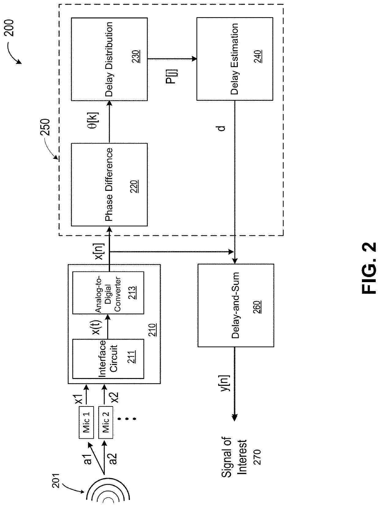
[0025]FIG. 2 is a simplified block diagram illustrating an acoustic signal processing system according to various embodiments of the present invention. As shown in FIG. 2, an acoustic signal processing system 200 includes an input module 210, and a signal processing circuit 250. In some embodiments, signal processing circuit 250 can include a phase-difference module 220, a delay distribution module 230, and a delay estimation module 240. Acoustic signal processing system 200 can also include a delay-and-sum module 260 to obtain a signal of interest 270.
[0026]As illustrated in FIG. 2, input module 210 is configured to receive at least two acoustic signals via at least two acoustic sensors, convert the at least two acoustic signals into at least two channels of analog signals and, subsequently, at least two channels of digital signals. In the example of FIG. 2, input module 210 can include a microphone interface circuit 211 and an analog-to-digital converter 213. Microphone interface ...
PUM
 Abstract
Description
Claims
Application Information