Safeguarded germical lighting device

a germicidal lighting and safety technology, applied in water installations, disinfection, construction, etc., can solve the problems of skin cancer or other health-related problems, is not practical to rely on user compliance with the safety practices of uv germicidal lighting, and loses energy, so as to increase the energy consumption of uv light sources and reduce the distance to the surface to be cleaned. , the effect of germicidal cleaning

Inactive Publication Date: 2021-10-07
ALEDDRA INC
View PDF3 Cites 2 Cited by
  • Summary
  • Abstract
  • Description
  • Claims
  • Application Information

AI Technical Summary

Benefits of technology

[0013]The germicidal effect of the UV light is proportional to the intensity of the UV light source. When the energy consumption of the UV light source is kept constant, the intensity of the UV light source remains constant for any given distance. However, if the distance of the UV light source to the surface to be cleaned is decreased, the germicidal cleaning effect may be increased without increasing the energy consumption of the UV light source. Therefore, in some embodiments, the upholder may have an adjustable mechanical structure for adjusting the position of the light head, and in the germicidal lighting mode, the first light head may be positioned within 30 cm of the surface illuminated by the lighting device for more effective germicidal cleaning.

Problems solved by technology

It is also known that direct exposure of human skin to UV light may lead to skin cancer or other health-related issues.
In a residential setting with children, however, it is not practical to rely on user compliance with the safety practices of UV germicidal lighting.
Firstly, it saves energy that would be lost due to unnecessary UV lighting.
This means that a user may not be able to tell whether the first light source is on by simply looking at the first light source.
However, if the distance of the UV light source to the surface to be cleaned is decreased, the germicidal cleaning effect may be increased without increasing the energy consumption of the UV light source.

Method used


Image

  • Safeguarded germical lighting device
  • Safeguarded germical lighting device
  • Safeguarded germical lighting device

Examples


example implementations

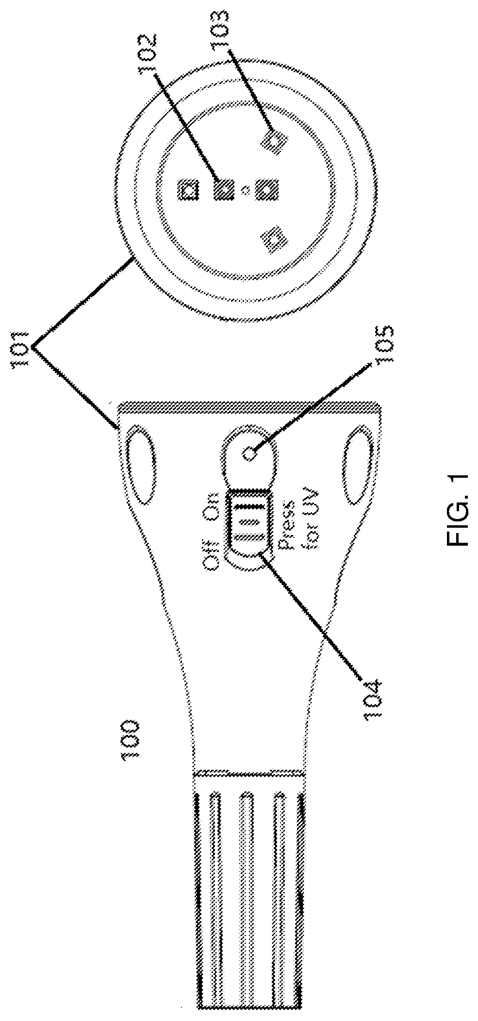
[0020]FIG. 1 shows an embodiment of the lighting device of the present disclosure in the form of an LED (Light Emitting Diode) flashlight 100. The light head 101 houses two light sources. The first light source 102 comprises two UV LEDs, and the second light source 103 comprises three white light LEDs. A user flips the switch 104 to turn on the second light source 103 for the general lighting mode operation. To activate the first light source 102 for the germicidal lighting mode operation, the user must keep pressing the switch 104. Once the user stops pressing the switch 104, the first light source 102 is turned off. Both the first light source 102 and the second light source 103 are on at the same time when the user is pressing the switch 104. When the switch 104 is at the OFF position, pressing the switch will not activate the first light source 102. The LED indicator 105 will light up when the first light source 102 is on, indicating to the user that the germicidal lighting is a...


PUM

PropertyMeasurementUnit
wavelengthaaaaaaaaaa
wavelength rangeaaaaaaaaaa

Abstract

A lighting device comprises a light head, two light sources, and a safeguard mechanism. The light head houses the two light sources. The first light source emits predominantly ultraviolet (UV) light (<400 nm) for germicidal illumination, and the second light source emits predominantly visible light (>400 nm) for general lighting. The lighting device may operate in two modes. The first operation mode is the general lighting mode, where the second light source is on for providing general lighting. The second operation mode is the germicidal lighting mode, where the first light source is on for providing germicidal lighting. The safeguard mechanism prevents the first light source in the germicidal lighting mode from turning on and causing accidental human exposure to the UV light from the first light source.

Description

BACKGROUNDTechnical Field[0001]The present disclosure pertains to the field of lighting devices and, more specifically, proposes a safeguarded germicidal lighting device.Description of Related Art[0002]UV light is known to be effective in killing bacteria and viruses and thus has been used in germicidal lighting applications. It is also known that direct exposure of human skin to UV light may lead to skin cancer or other health-related issues. As a result, UV-based germicidal lighting device is generally placed in a concealed environment or at an upper room location to avoid directly shining on people. However, there are situations where it is necessary or desirable to use UV light to clean viruses and bacteria on a desktop surface at close distances. In these situations, the UV light should be turned on only when no one is around. This approach requires user compliance and is used in medical environments where users are properly trained in safety practices. In a residential setting...

Claims


Application Information

Patent Timeline
Patent Type & Authority Applications(United States)
IPC IPC(8): A61L2/10A61L2/26
CPCA61L2/10A61L2/26A61L2202/11A61L2202/25A61L2209/12
Inventor MAA, CHIA-YIUYU, CHUN-TE
Owner ALEDDRA INC
Why Eureka
Try Eureka