
Clutch device

a technology of clumping and retaining rod, which is applied in the direction of clumping, friction clutch, coupling, etc., can solve the problems of damaged or broken clumping outer surfaces, and achieve the effect of enhancing the anti-abrasion properties of the clumping pla

Active Publication Date: 2021-10-07
EXEDY CORP
View PDF0 Cites 1 Cited by
  • Summary
  • Abstract
  • Description
  • Claims
  • Application Information

AI Technical Summary

Benefits of technology

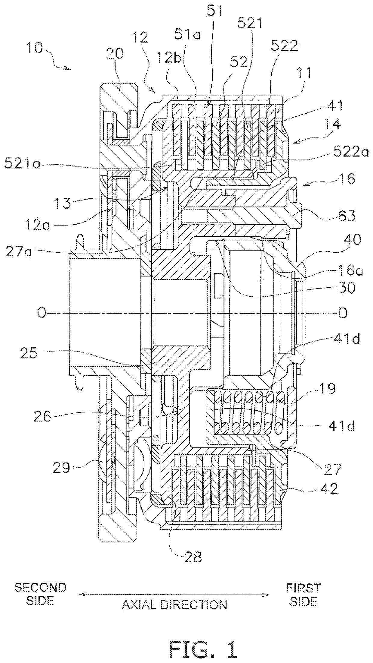
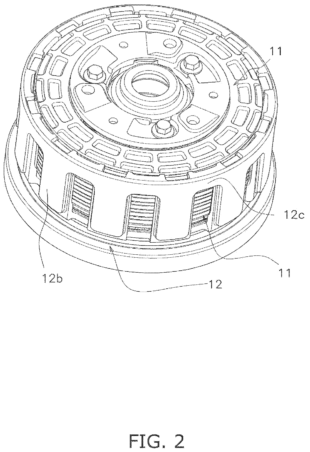
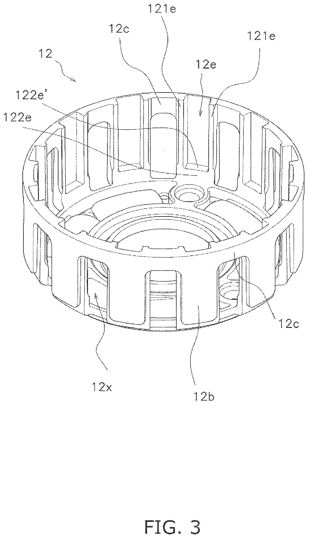
This patent enhances the anti-abrasive properties of a clutch plate by adding cover portions to the clutch outer that cover the teeth of the clutch plate. The cover portions are attached to each other at the distal ends through coupling portions, preventing them from flaring radially outward when centrifugal forces act on the clutch outer. This strengthens the clutch outer. Additionally, the coupling portions allow lubricating oil to easily discharge. Overall, this enhances the performance of the clutch plate.

Problems solved by technology

However, the following is concerned when the clutch outer is not made of a steel plate: If centrifugal forces act on the engaging tooth portion protruding from the clutch outer, stresses concentrate thereon whereby the clutch outer is damaged or broken.

Method used


Image

  • Clutch device
  • Clutch device
  • Clutch device

Examples


modification 1

[0100]In the embodiment described above, the clutch outer 12 includes the coupling portions 12c. However, the structure of the clutch outer 12 is not limited to this. The clutch outer 12 may not include the coupling portions 12c. In this case, the clutch outer 12 can be made lightweight.

modification 2

[0101]The embodiment described above has been explained with the clutch center 13 as an exemplary first rotor and the pressure plate 14 as an exemplary second rotor. In other words, in the embodiment described above, the present invention has been applied to a so-called pull-type clutch device that the pressure plate 14 is moved to the first side in the axial direction so as to tum off the clutch plate 11. However, the present invention is similarly applicable to a so-called push-type clutch device as well.

[0102]FIG. 10 shows a push-type clutch device 110.

[0103]In the push-type clutch device 110, a pressure plate 114 corresponds to the first rotor; a clutch center 113 corresponds to the second rotor; a support plate 116 corresponds to the support member.

[0104]Specifically, in the push-type clutch device 110, the pressure plate 114, the clutch center 113, and the support plate 116 are disposed from the second side to the first side in the axial direction. The pressure plate 114 and t...

modification 3

[0107]The configuration of the clutch outer 12 is not limited to that in the embodiment described above. For example, in the embodiment described above, the bottom portion 12a and the cover portions 12b are integrated in the clutch outer 12. However, these portions 12a and 12b may be provided as separate members. The method of forming the bottom portion 12a and the cover portions 12b in the clutch outer 12 is not limited to aluminum die casting.


PUM


Abstract

A clutch device includes a clutch plate and a clutch outer. The clutch plate includes a plurality of teeth circumferentially disposed apart from each other. The clutch outer includes a bottom portion, a plurality of cover portions, and a plurality of openings. The bottom portion has a disc shape and is greater in diameter than the clutch plate. The cover portions axially extend from an outer peripheral edge of the bottom portion so as to cover the teeth. The cover portions are circumferentially disposed apart from each other. Each opening is disposed between each adjacent pair of the cover portions. Each opening is radially opened.

Description

CROSS-REFERENCE TO RELATED APPLICATIONS[0001]This application claims priority to Japanese Patent Application No. 2020-065998, filed Apr. 1, 2020. The contents of that application are incorporated by reference herein in their entirety.TECHNICAL FIELD[0002]The present invention relates to a clutch device.BACKGROUND ART[0003]In general, motorcycles (a two-wheeled motorcycle, a buggy, etc.) use a clutch device so as to allow or block transmitting power from an engine to a transmission. The clutch device includes a clutch outer, a clutch center, a clutch plate, and a pressure plate. The clutch outer is coupled to an engine crankshaft side. The clutch center is coupled to a transmission side. The clutch plate is disposed between the clutch outer and the clutch center so as to allow or block transmission of power. The pressure plate is provided for pressing the clutch plate.[0004]The clutch plate includes teeth protruding radially outward. The teeth are used for engagement with the clutch ...

Claims


Application Information

Patent Timeline
Patent Type & Authority Applications(United States)
IPC IPC(8): F16D13/64F16D13/52
CPCF16D13/648F16D13/52F16D13/58F16D13/74F16D2300/26F16D13/644F16D13/62
Inventor KITAZAWA, HIDENORIMATSUYOSHI, NORIKO
Owner EXEDY CORP
Learn More