Electrolyte measuring device
a technology of electrolyte and measuring device, which is applied in the direction of measurement device, instruments, scientific instruments, etc., can solve the problem that publicly known technologies do not take sufficient measures to detect failure in devices, and achieve the effect of high degree of sensitivity
- Summary
- Abstract
- Description
- Claims
- Application Information
AI Technical Summary
Benefits of technology
Problems solved by technology
Method used
Image

Examples
first embodiment
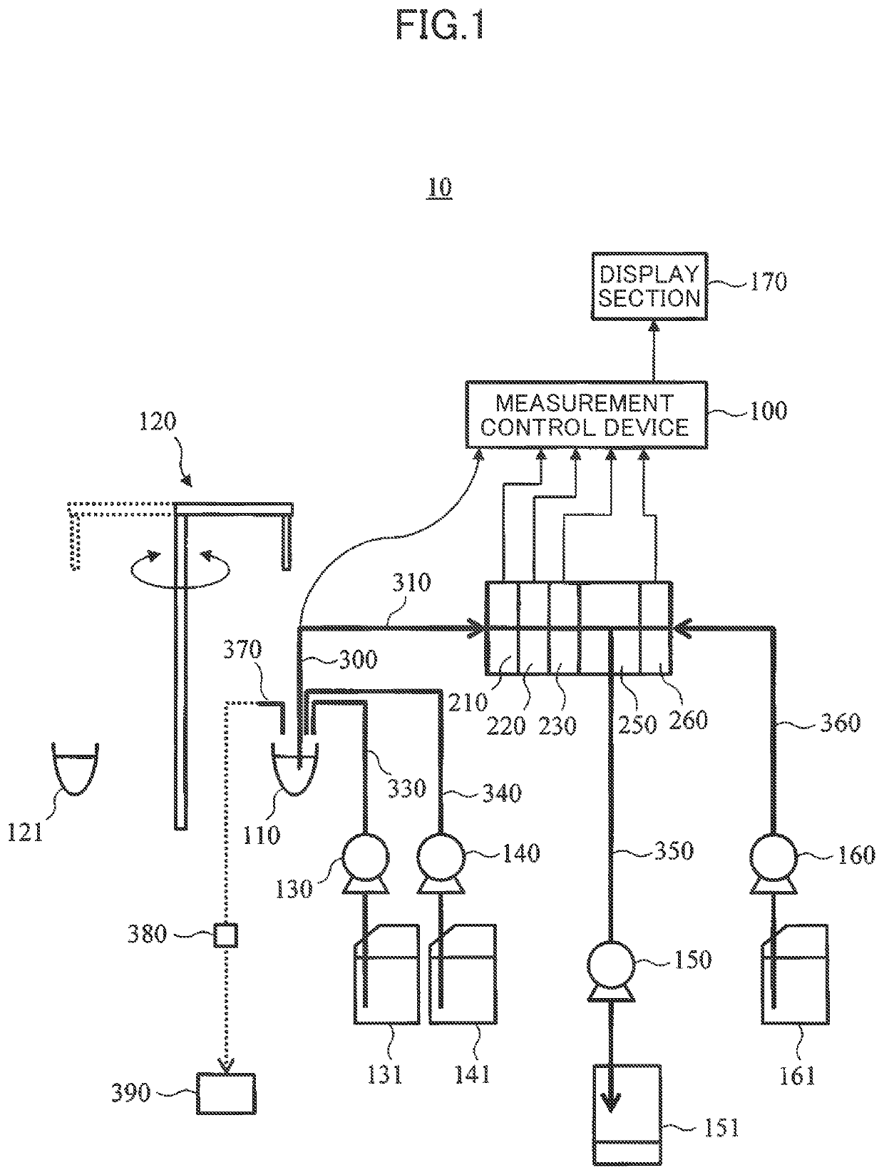
[0027]FIG. 1 is a schematic diagram showing a rough configuration of an electrolyte measuring device 10 according to a first embodiment. The electrolyte measuring device 10: is an electrolyte measuring device equipped with an ion-selective electrode of a flow cell type; and has a measurement control device 100, a dilution tank 110, a specimen dispensing mechanism 120, a diluent liquid dispensing mechanism 130, an internal standard liquid dispensing mechanism 140, a liquid feeding mechanism 150, a reference electrode liquid feeding mechanism 160, a display section 170, a Cl-ion-selective electrode 210, a K-ion-selective electrode 220, an Na-ion-selective electrode 230, a liquid junction section 250, a reference electrode 260, a waste liquid nozzle 370, a drive mechanism for waste liquid nozzle (not shown in the figure), a waste liquid valve 380, and a waste liquid mechanism 390.
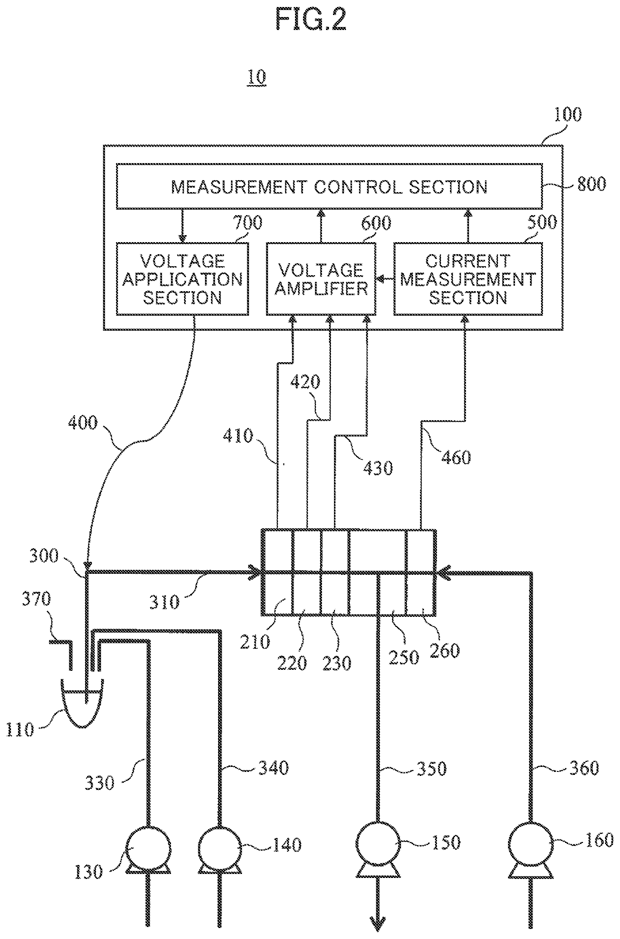
[0028]The measurement control device 100 functions as: a measurement section to manage measurement in the e...
modified example
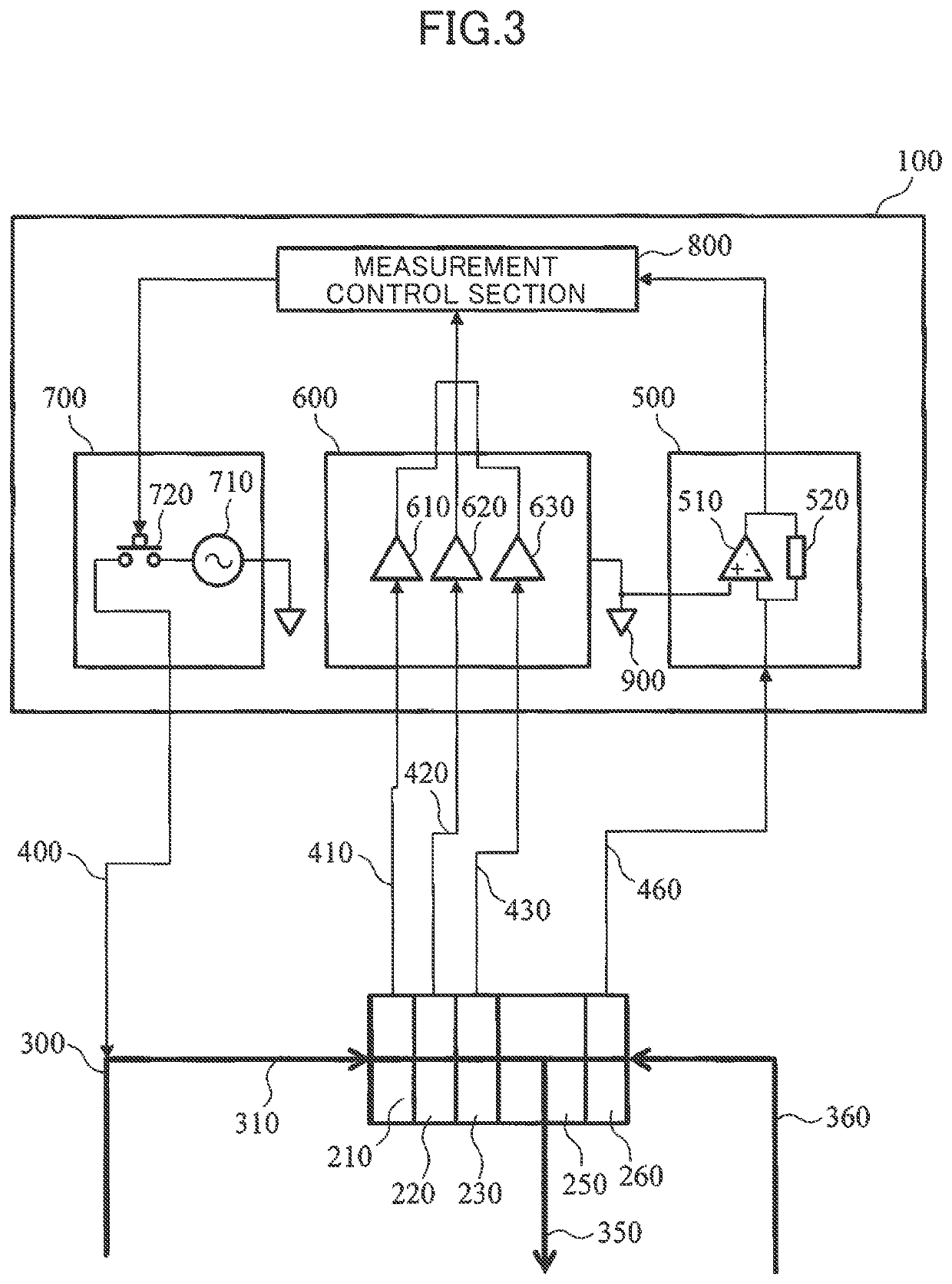
[0061]An example modified from the first embodiment is shown in FIG. 5. In the modified example, a power source 710 in a voltage application section 700 is excluded and an analog switch 720 is directly connected to a ground terminal 900. In general, an interface potential exists between a metal and a solution or an electrode and a solution. When the interface potential is sufficiently large, that can be used as a substitute for a power source 710. In the modified example, since the configuration is simpler than the first embodiment, it is possible to reduce the cost, simplify the maintenance, and reduce the risk of failure.
second embodiment
[0062]An electrolyte measuring device according to a second embodiment is hereunder explained in reference to FIG. 6 and FIG. 7. In the second embodiment, the overall configuration (FIG. 1) is the same as the first embodiment. In the second embodiment, the configuration of a measurement control device 100 is different from the first embodiment. [0050]
[0063]The details of the configuration of the measurement control device 100 according to the second embodiment are explained in reference to FIG. 6 and FIG. 7. To a component in FIG. 6 and FIG. 7 identical to a component in a measurement control device 100 according to the first embodiment, a reference code identical to a reference code in FIG. 2 and FIG. 3 is given and a duplicated explanation is omitted hereunder.
[0064]An electrolyte measuring device according to the second embodiment measures an electric current (hereunder referred to as a “natural electric current”) flowing steadily in a reference electrode 260, instead of detectin...
PUM
| Property | Measurement | Unit |
|---|---|---|
| voltage | aaaaa | aaaaa |
| output voltage | aaaaa | aaaaa |
| volume | aaaaa | aaaaa |
Abstract
Description
Claims
Application Information
 - R&D
- Intellectual Property
- Life Sciences
- Materials
- Tech Scout
- Unparalleled Data Quality
- Higher Quality Content
- 60% Fewer Hallucinations
Browse by: Latest US Patents, China's latest patents, Technical Efficacy Thesaurus, Application Domain, Technology Topic, Popular Technical Reports.
© 2025 PatSnap. All rights reserved.Legal|Privacy policy|Modern Slavery Act Transparency Statement|Sitemap|About US| Contact US: help@patsnap.com