Electric Iris

a technology of iris and electric field, applied in the field of electric iris, can solve the problems of affecting the accuracy of the image sensor, introducing vibration, and damaging the image sensor of the optical system such as the video camera or still image camera, and introducing high intensity light sources such as lasers

Active Publication Date: 2021-10-14
THE BOEING CO
View PDF3 Cites 0 Cited by
  • Summary
  • Abstract
  • Description
  • Claims
  • Application Information

AI Technical Summary

Benefits of technology

[0009]Another example of the present disclosure provides an optical system comprising an optical lens. A number of transparent conductive layers is coupled to an optical surface of the optical lens. A liquid crystal film is separated into a number of portions by the number of transparent conductive layers. A transmissive state of each portion from the number of portions of the liquid crystal film with respect to light is configured to change in response to application of a voltage to the number of transparent conductive layers. A controller is configured to selectively apply the voltage to change the transmissive state of one or more portions from the number of portions of the liquid crystal film between transparent and reflective to thereby change an amount of light passing through the optical lens to an image sensor.

Problems solved by technology

High intensity light sources such as lasers can damage an image sensor of an optical system such as a video camera or still image camera.
The mechanical iris requires a motor, however small, that may introduce vibration.
Movement of these mechanical plates, along with the motor that drives them, may cause vibration which may affect the accuracy of the image sensor.
Additionally, the mechanical movement may produce unwanted delay in adjusting the amount of light reaching the optical image sensor.

Method used


Image

  • Electric Iris
  • Electric Iris
  • Electric Iris

Examples


Embodiment Construction

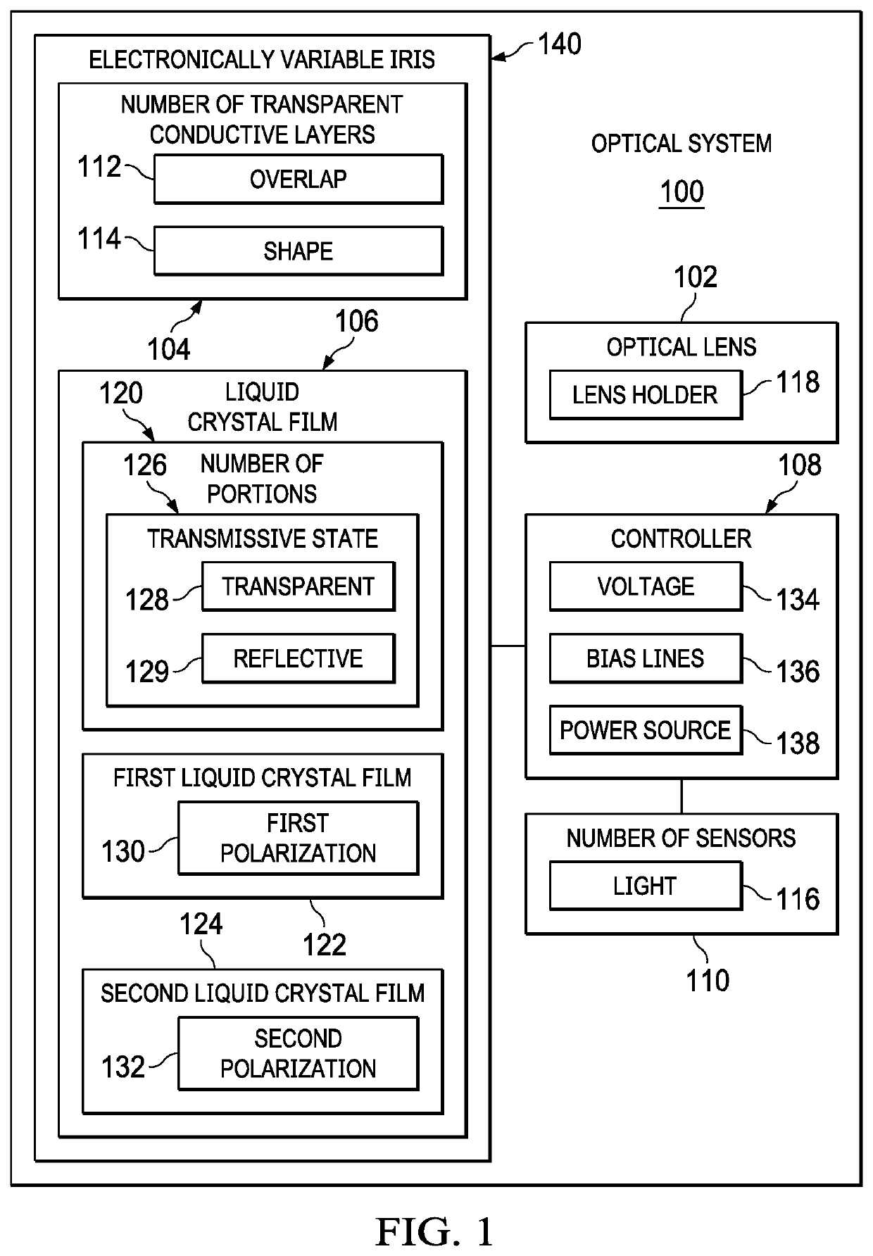
[0023]The illustrative examples recognize and take into account one or more different considerations. For example, the illustrative examples recognize and take into account that it would be desirable to alter the size of the aperture of an optical system quicker than what is typically provided by a mechanical iris. Further it would be desirable to alter the size of the aperture of an optical system automatically upon the detection of high-intensity light that would damage an optical image sensor if such high-intensity light were to reach the optical image sensor unhindered.

[0024]The illustrative examples recognize and take into account that it would be desirable to electronically alter the size of the aperture of an optical system to remove the motion and vibration caused by a typical mechanical iris.

[0025]Thus, the illustrative examples provide an electrically variable iris for an optical system that operates to reduce or increase the aperture of the optical system in a fraction of...


PUM

PropertyMeasurementUnit
transparentaaaaaaaaaa
transparent conductiveaaaaaaaaaa

Abstract

An optical system with an electronically variable iris. The optical system comprises an optical lens. A number of transparent conductive layers is coupled to an optical surface of the optical lens. A liquid crystal film is separated into a number of portions by the number of transparent conductive layers, wherein a transmissive state of each portion, from the number of portions of the liquid crystal film, with respect to light is configured to change in response to application of a voltage to the number of transparent conductive layers.

Description

CROSS-REFERENCE TO RELATED APPLICATIONS[0001]This application is related to U.S. Pat. No. 9,415,745, issued on Aug. 16, 2016 and U.S. Pat. No. 9,835,914, issued on Dec. 5, 2017. Both patents are incorporated by reference herein in their entirety.BACKGROUND INFORMATION1. Field[0002]The present disclosure relates generally to electrical f-stops for an optical lens, and in particular, to an electrically controlled iris which operates without motion or vibration to protect image sensors from sudden bright lights or lasers.2. Background[0003]High intensity light sources such as lasers can damage an image sensor of an optical system such as a video camera or still image camera. At their most basic, optical systems or cameras are sealed boxes with a small hole or aperture that lets light in to capture an image on a light-sensitive surface such as photographic film or a digital image sensor.[0004]Optical systems have various mechanisms to control how the light falls onto the light-sensitive...

Claims


Application Information

Patent Timeline
Patent Type & Authority Applications(United States)
IPC IPC(8): G02F1/1347G02F1/139G02F1/1335G02B5/30H04N5/225C09K19/00
CPCG02F1/13471G02F1/139C09K19/00G02B5/3016H04N5/2254G02F1/133528G03B9/02G02F1/133G02F1/13318G02F1/1333G02F1/1343G02F1/13718G02F1/13478G02F1/134327G02F2201/58G02F1/133526G03B9/06G03B17/12H04N23/55
Inventor CLEMEN, JR., MARK JOSEPH
Owner THE BOEING CO
Why Eureka
Try Eureka