
Bidirectional low tearing strength spacer textile using warp knitting

a spacer textile and low tearing strength technology, applied in knitting, ornamental textile articles, pedestrian/occupant safety arrangements, etc., can solve the problems of excessive consumption of adhesive applied during warp knitting, inability to obtain the required tearing property values in both directions, and inability to easily unwound, etc., to achieve low tearing strength, easy to unwound, and easy to tear

Pending Publication Date: 2021-10-28
TKG ECO MATERIAL CO LTD
View PDF0 Cites 0 Cited by
  • Summary
  • Abstract
  • Description
  • Claims
  • Application Information

AI Technical Summary

Benefits of technology

The present invention provides a spacer textile that can be easily ruptured when an airbag is deployed due to a certain external force applied thereto regardless of the longitudinal and transverse directions, and has a low tearing strength in both longitudinal and transverse directions while reducing the amount of adhesive used. The textile has a unique structure that allows for easy unwinding and tearing of the yarn during tensioning, resulting in a low tearing strength. The additional thread is formed discontinuously at a portion being overlapped with the main thread, making it easier to implement low tearing strength during longitudinal tensioning. Overall, the invention provides a textile that is easy to use and has low tearing strength.

Problems solved by technology

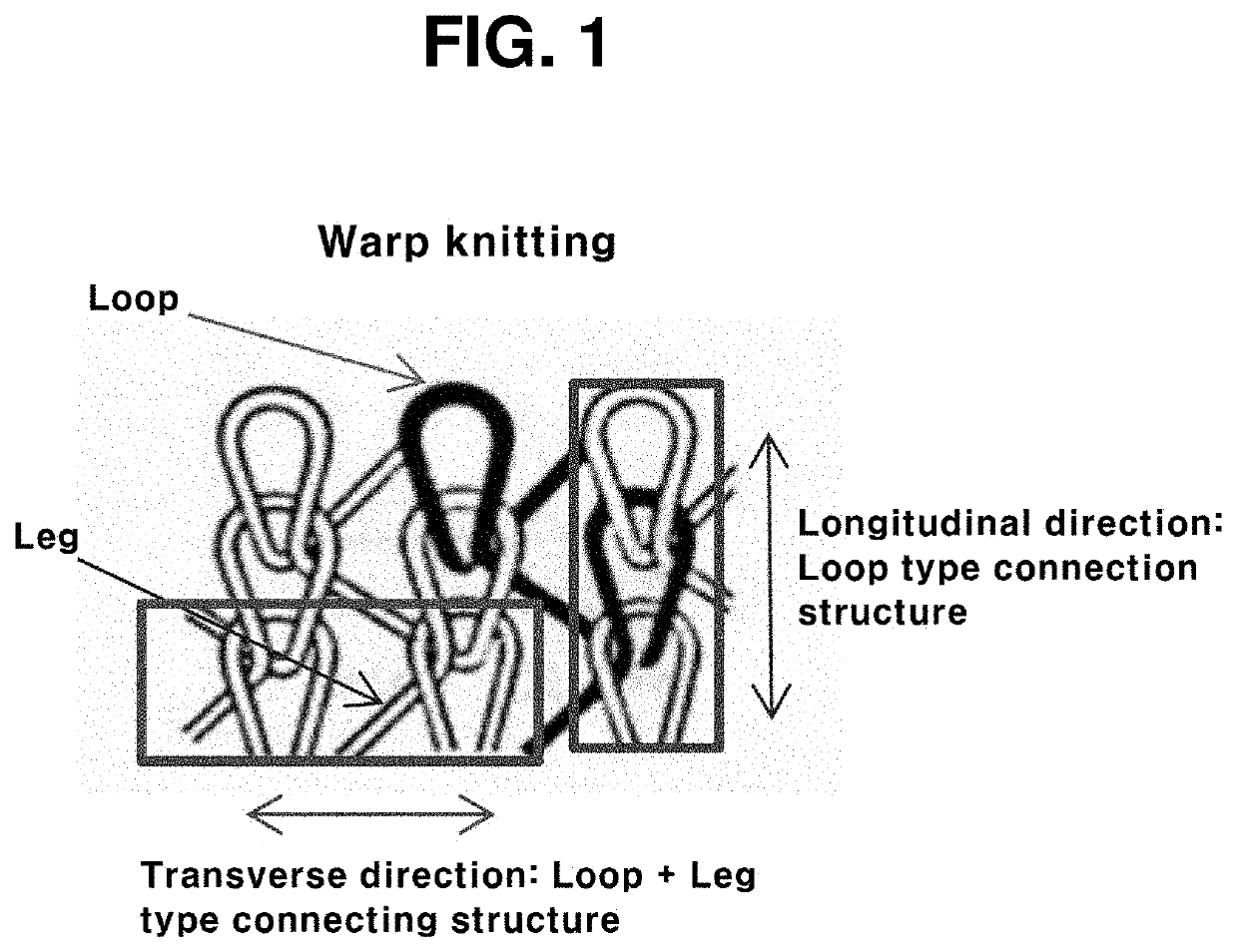
However, in the case of a currently applied 3D warp knitting (Double Raschel) product, although there is no problem in expressing the feeling of cushion, it should be easily torn regardless of the longitudinal and transverse directions when it is used in the airbag deployment line, but since the structure in the longitudinal and transverse directions is different due to the characteristics of warp knitting products, there is a limit to obtain the required tearing property values in both directions, and thus, there is a problem that it is not easily torn in both longitudinal and transverse directions.
In addition, even in the case of warp knitting used for a portion of a conventional airbag deployment line, there is a problem in that an excessive amount of an adhesive applied during warp knitting is consumed.
In other words, in the case of conventional warp knitting, the gap between loops is large, so a significant amount of the injected adhesive seeps through the gaps of the warp knitting loops and is not used for actual fabric bonding, thereby being a factor of cost increase.

Method used


Image

  • Bidirectional low tearing strength spacer textile using warp knitting
  • Bidirectional low tearing strength spacer textile using warp knitting
  • Bidirectional low tearing strength spacer textile using warp knitting

Examples


Embodiment Construction

[0023]Hereinafter, embodiments of the present invention will be described in more detail with reference to the accompanying drawings, but the following embodiments are for the purpose of explanation only, and are not intended to limit the scope of the present invention.

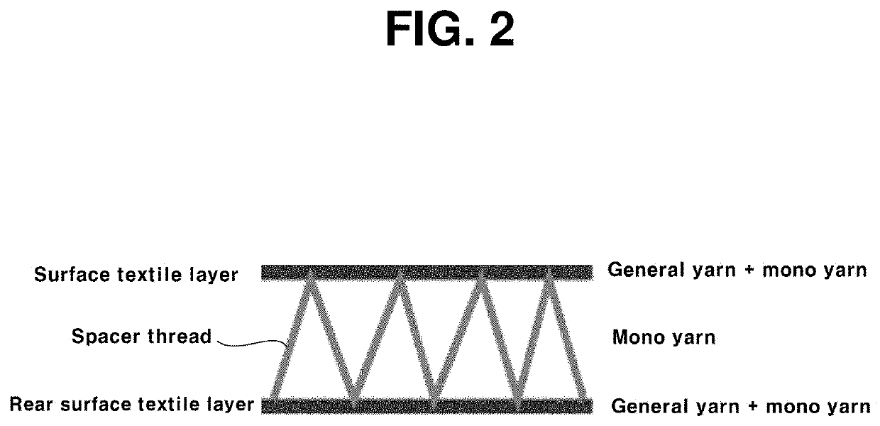
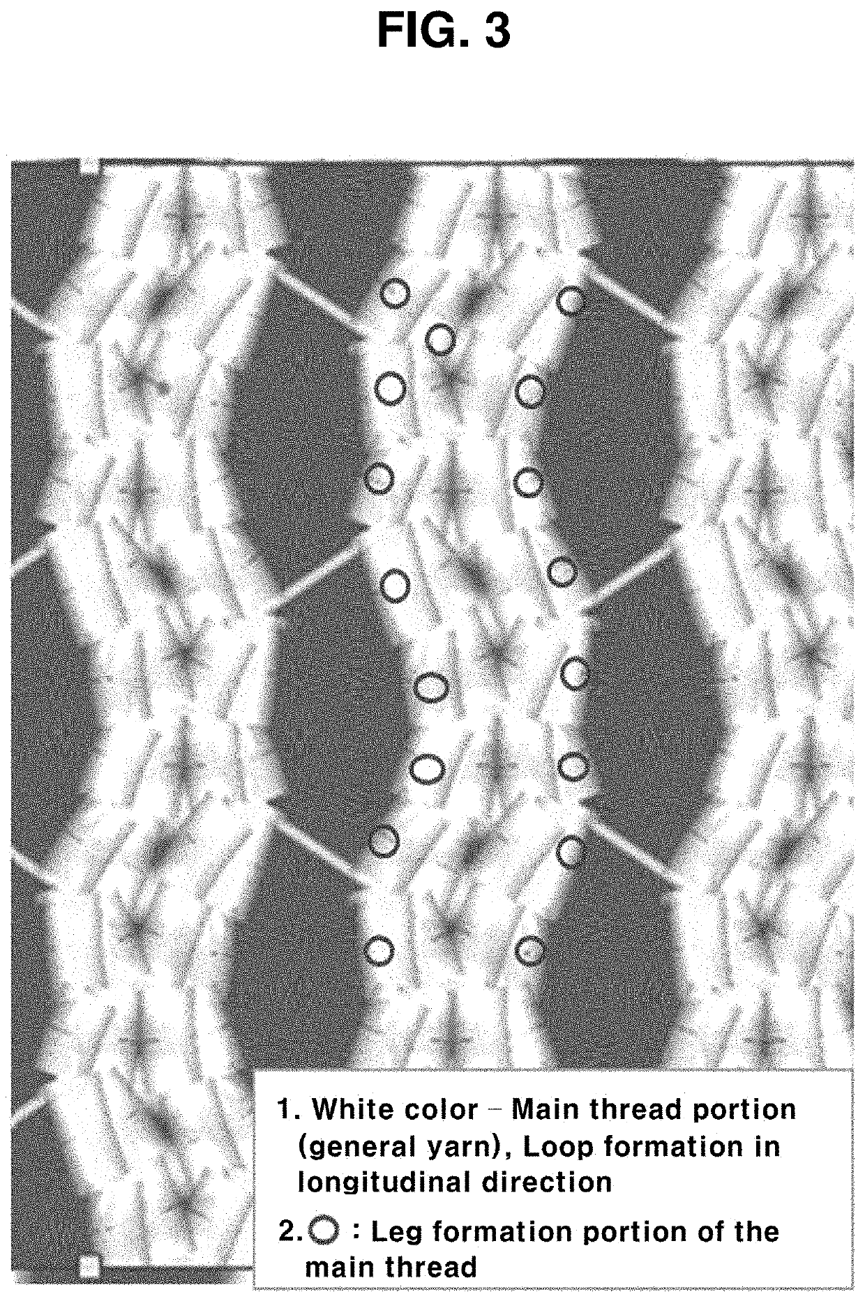
[0024]FIG. 2 is a schematic diagram showing a structure of a spacer textile according to an embodiment of the present invention, and FIGS. 3 and 4 are schematic diagrams showing structures of an outer side surface and an inner side surface of a surface textile layer according to an embodiment of the present invention.

[0025]Referring to FIGS. 2 to 4, a spacer textile according to the present invention includes a surface textile layer, a rear surface textile layer, and a spacer thread connecting the textile layers.

[0026]The surface textile layer and the rear surface textile layer are separated from each other and are connected by spacer threads to have a structure that is symmetrical on the sides opposite from each othe...


PUM

PropertyMeasurementUnit
tearing strengthaaaaaaaaaa
structureaaaaaaaaaa
thread structureaaaaaaaaaa

Abstract

The present invention relates to a bidirectional low tearing strength spacer textile using warp knitting, more particularly, relates to a spacer textile comprising a surface textile layer, a rear surface textile layer, and a spacer thread connecting the textile layers, wherein the surface textile layer and the rear surface textile layer include a main thread provided with a plurality of open loops formed with openings in a longitudinal direction.

Description

CROSS-REFERENCE TO RELATED APPLICATIONS[0001]This application claims priority to Korean Patent Application No. 10-2020-0051800 filed on Apr. 28, 2020, the disclosure of which is expressly incorporated herein by reference.STATEMENT RE: FEDERALLY SPONSORED RESEARCH / DEVELOPMENT[0002]Not ApplicableBACKGROUNDTechnical Field[0003]The present invention relates to a bidirectional low tearing strength spacer textile using warp knitting.Background[0004]Currently, the use of 3D warp knitting (Double Raschel) products that can express the same cushioning feeling from low-cost polyurethane foam, which is an existing vehicle cushioning material, is expanding due to increased demand for high-end vehicles and eco-friendly products.[0005]As a prior art, registered utility model No. 20-0238028 discloses warp knitted paper having excellent breathability and cushioning properties. In addition, FIG. 1 shows a structure of conventional warp knitting in the longitudinal and transverse direction, and shows...

Claims


Application Information

Patent Timeline
Patent Type & Authority Applications(United States)
IPC IPC(8): D04B21/16B32B5/02B32B5/06B32B5/26
CPCD04B21/165B32B5/026B32B2307/582B32B5/26B32B5/06D04B21/14D10B2403/021D10B2505/124D04B21/20B60R21/235B60R2021/23509B60R2021/23552
Inventor KIM, MAN YOUNGCHOI, DAE KUNSEO, JUN HYEONG
Owner TKG ECO MATERIAL CO LTD
Learn More