Programmable analog beamformer
a beamformer and analog technology, applied in the field of beamformers, can solve problems such as phase delay, and achieve the effect of reducing power
- Summary
- Abstract
- Description
- Claims
- Application Information
AI Technical Summary
Benefits of technology
Problems solved by technology
Method used
Image

Examples
Embodiment Construction
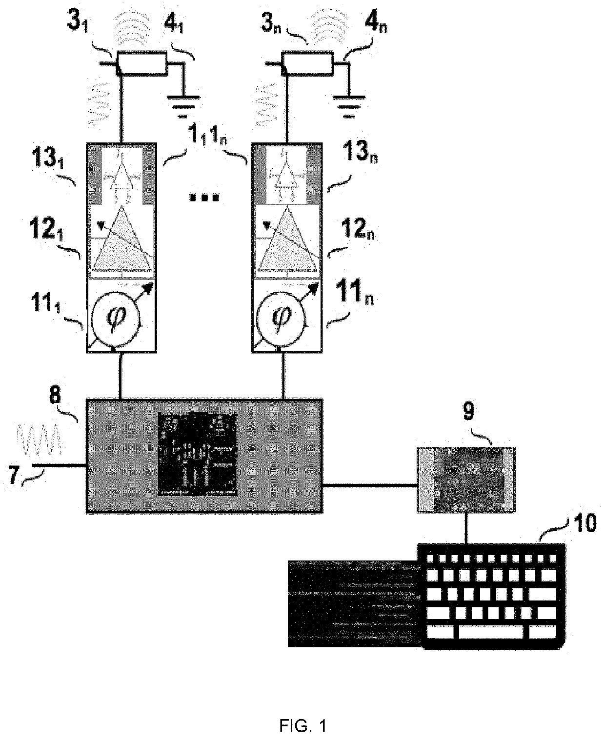
[0021]Simplified block diagram of programmable analog beamformer is shown in FIG. 1. Input Radio Frequency (RF) sine signal 7 at frequency of user choice enters the system (which can come from a function generator or a builtin signal generator embedded in the beamformer). The sine signal branches out to n channels 11, 12 . . . 1n in buffer circuit 8 (details not shown). Branching can be done via a buffer amplifier, or directing wiring to n channels as inputs of channels are high impedance and there will be no loading effect.
[0022]Each channel 11, 12 . . . 1n has three parts: phase shifters 111, 112 . . . 11n; Amplitude control units 121, 122 . . . 12n; and final power amplifiers 131, 132 . . . 13n. These three parts generate same RF sine signal of buffer 8 with different phase and amplitude at outputs to loads 31, 32 . . . 3n. Phases and amplitudes in each channel is set through user interface software by users.
[0023]Loads 31, 32 . . . 3n can be piezoelectric transducers in ultrasou...
PUM
 Abstract
Description
Claims
Application Information
 - R&D
- Intellectual Property
- Life Sciences
- Materials
- Tech Scout
- Unparalleled Data Quality
- Higher Quality Content
- 60% Fewer Hallucinations
Browse by: Latest US Patents, China's latest patents, Technical Efficacy Thesaurus, Application Domain, Technology Topic, Popular Technical Reports.
© 2025 PatSnap. All rights reserved.Legal|Privacy policy|Modern Slavery Act Transparency Statement|Sitemap|About US| Contact US: help@patsnap.com