Line narrowing module, gas laser apparatus, and electronic device manufacturing method

a laser apparatus and narrowing module technology, applied in the direction of instruments, photomechanical equipment, optical elements, etc., can solve problems such as reducing resolution

Active Publication Date: 2021-10-28
GIGAPHOTON
View PDF0 Cites 0 Cited by
  • Summary
  • Abstract
  • Description
  • Claims
  • Application Information

AI Technical Summary

Benefits of technology

[0009]One aspect of the present disclosure may be a line narrowing module including a prism including an entrance side surface that light enters, an exit side surface from which the light is emitted, and a bottom surface, and configured to wavelength-disperse the light having entered the entrance side surface and to emit the light from the exit side surface; a holder portion having a stationary surface on which the bottom surface of the prism is secured; a rotary mechanism portion including a rotary stage on which the holder portion is secured, the rotary stage being configured to rotate the prism around an axis perpendicular to a dispersion plane of the light emitted from the prism; a drive unit configured to rotate the rotary stage; and a grating configured to reflect the light emitted from the prism, a centroid of the prism, a centroid of the holder portion, and a centroid of the rotary stage being located on the axis.
[0010]Another aspect of the present disclosure may be a gas laser apparatus including a line narrowing module, the line narrowing module including a prism including an entrance side surface that light enters, an exit side surface from which the light is emitted, and a bottom surface, and configured to wavelength-disperse the light having entered the entrance side surface and to emit the light from the exit side surface, a holder portion having a stationary surface on which the bottom surface of the prism is secured, a rotary mechanism portion including a rotary stage on which the holder portion is secured, the rotary stage being configured to rotate the pri

Problems solved by technology

Thus, if a projection lens is made of a material that transmits ultraviolet light such

Method used


Image

  • Line narrowing module, gas laser apparatus, and electronic device manufacturing method
  • Line narrowing module, gas laser apparatus, and electronic device manufacturing method
  • Line narrowing module, gas laser apparatus, and electronic device manufacturing method

Examples


embodiment 1

3. Description of line narrowing module of Embodiment 1

[0033]3.1 Configuration

[0034]3.2 Operation

[0035]3.3 Effect

embodiment 2

4. Description of line narrowing module of Embodiment 2

[0036]4.1 Configuration

[0037]4.2 Effect

embodiment 3

5. Description of line narrowing module of Embodiment 3

[0038]5.1 Configuration

[0039]5.2 Effect

[0040]Now, with reference to the drawings, embodiments of the present disclosure will be described in detail.

[0041]The embodiments described below illustrate some examples of the present disclosure, and do not limit contents of the present disclosure. Also, all configurations and operations described in the embodiments are not necessarily essential as configurations and operations of the present disclosure. The same components are denoted by the same reference numerals, and overlapping descriptions are omitted.

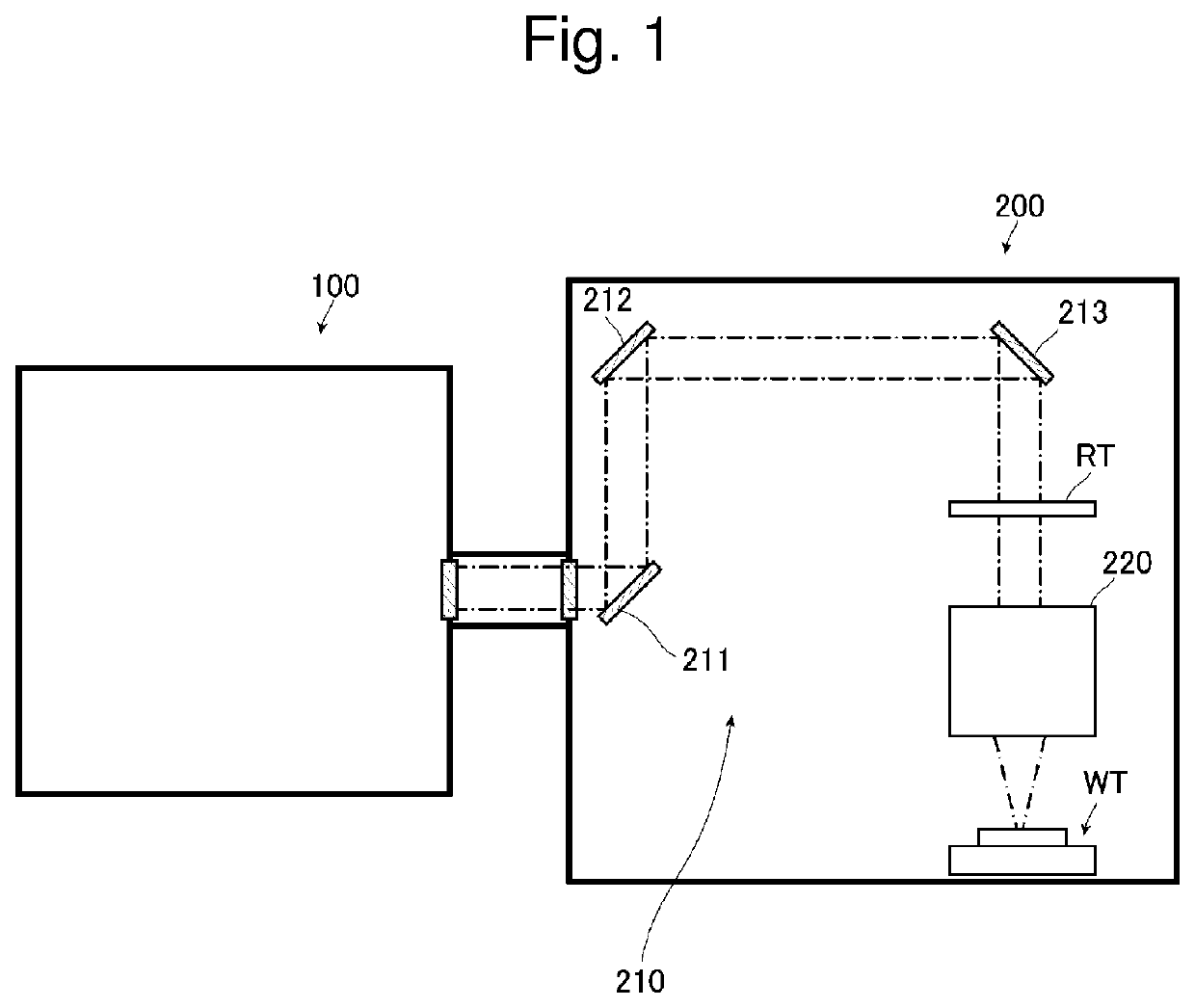
1. Description of Manufacturing Device Used in Exposure Process in Manufacture of Electronic Device

[0042]FIG. 1 is a schematic diagram of an exemplary configuration of the entire manufacturing device used in an exposure process in manufacture of an electronic device. As shown in FIG. 1, the manufacturing device used in the exposure process in manufacture of an electronic device includ...


PUM


Abstract

A line narrowing module includes a prism including an entrance side surface that light enters, an exit side surface from which the light is emitted, and a bottom surface, and configured to wavelength-disperse the light having entered the entrance side surface and to emit the light from the exit side surface; a holder portion having a stationary surface on which the bottom surface of the prism is secured; a rotary mechanism portion including a rotary stage on which the holder portion is secured, the rotary stage being configured to rotate the prism around an axis perpendicular to a dispersion plane of the light emitted from the prism; a drive unit configured to rotate the rotary stage; and a grating configured to reflect the light emitted from the prism, centroids of the prism, the holder portion, and the rotary stage being located on the axis.

Description

CROSS-REFERENCE TO RELATED APPLICATIONS[0001]The present application is a continuation application of International Application No. PCT / JP2019 / 007315, filed on Feb. 26, 2019, the entire contents of which are hereby incorporated by reference.BACKGROUND1. Technical Field[0002]The present disclosure relates to a line narrowing module, a gas laser apparatus, and an electronic device manufacturing method.2. Related Art[0003]Recently, improvement in resolution of semiconductor exposure apparatuses (hereinafter referred to as “exposure apparatuses”) has been desired due to miniaturization and high integration of semiconductor integrated circuits. For this purpose, exposure light sources that output light with shorter wavelengths have been developed. As the exposure light source, a gas laser apparatus is generally used in place of a conventional mercury lamp. For example, as a gas laser apparatus for exposure, a KrF excimer laser apparatus that outputs an ultraviolet laser beam having a wav...

Claims


Application Information

Patent Timeline
IPC IPC(8): H01S3/137G03F7/20
CPCH01S3/137H01S3/2251G03F7/70025H01S3/036H01S3/08004H01S3/08009H01S3/0971H01S3/104H01S3/134G03F7/70575H01S3/034G02B26/0883
Inventor IGARASHI, MIWAMATSUMOTO, SHINICHI
Owner GIGAPHOTON
Why Eureka
Try Eureka