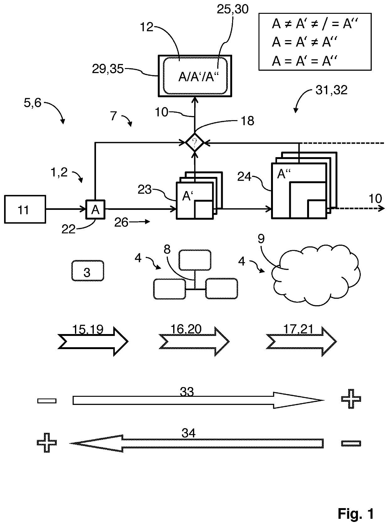
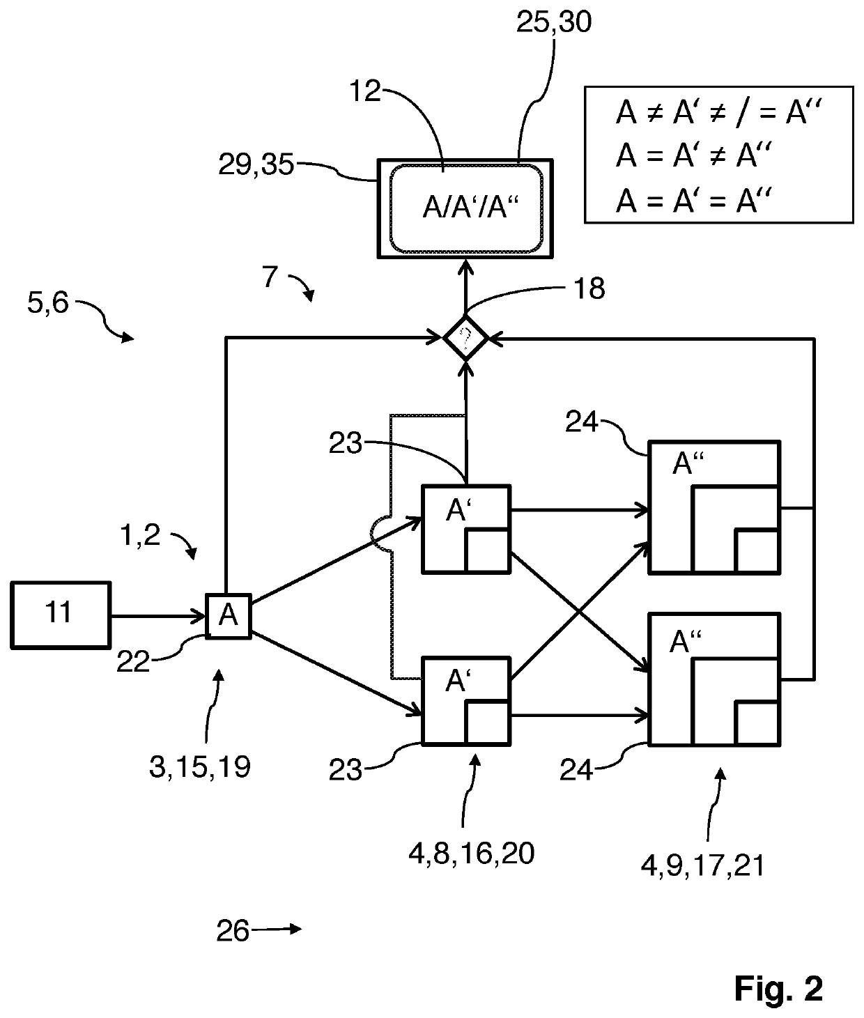
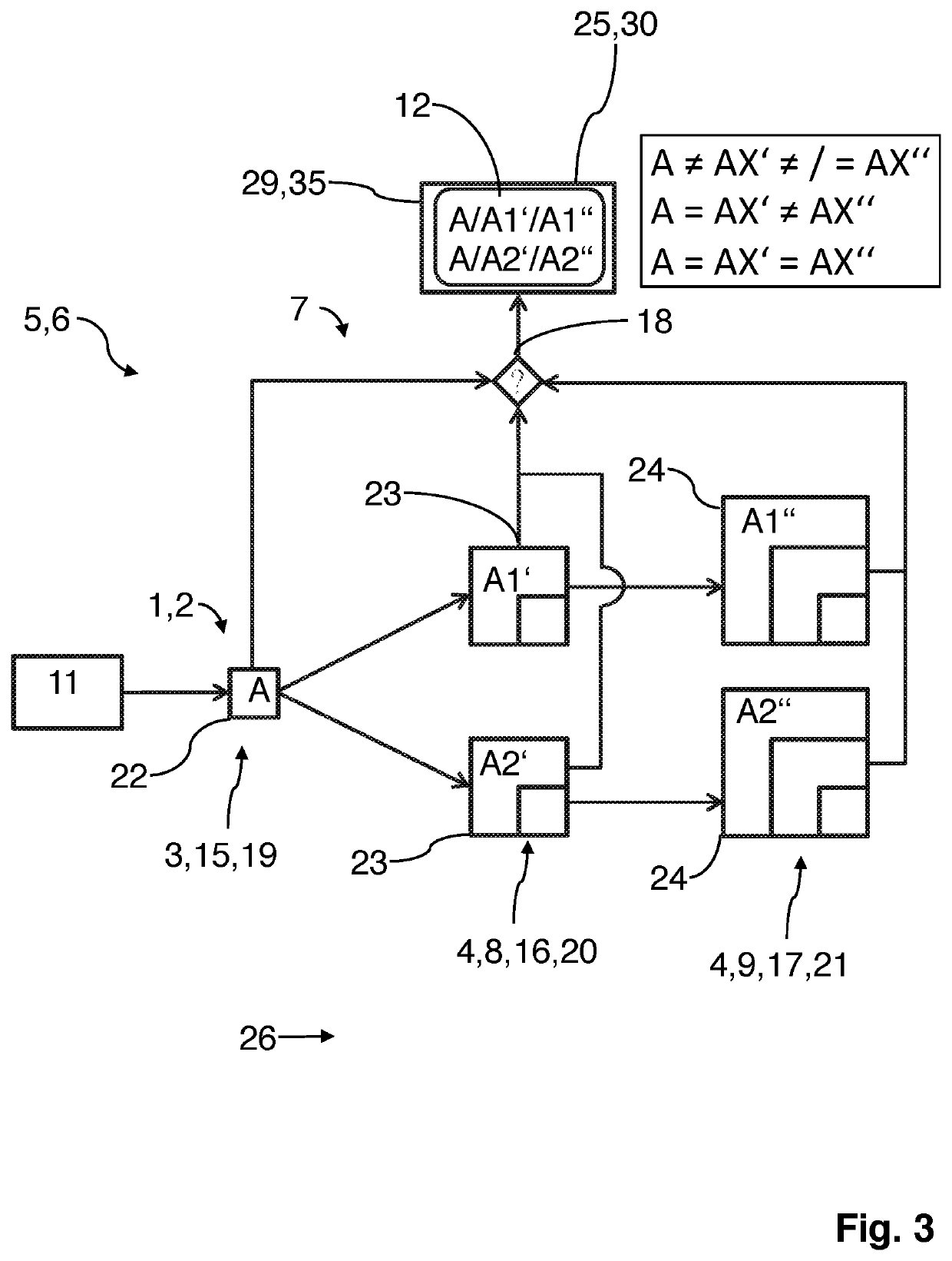
[0039]FIGS. 1-4 show different exemplary embodiments of a method according to the invention for reconstructing an output image 10, 22, 23, 24 and/or a sequence of output images 10, 22, 23, 24 (in the case of a video signal) from raw image data 11 (in particular, input images that have been recorded by an image recording device 1), wherein the raw image data 11 is processed in at least two consecutive and/or parallel reconstruction stages 15, 16, 17, and an output image 10, 22, 23, 24 and/or a corresponding sequence of reconstructed output images 10, 22, 23, 24 is output.
[0040]FIG. 5 shows a timeline 13 between the input 27 of raw image data 11, e.g. through the recording of a scene, and the output 28 after the image reconstruction. The details of the image reconstruction are described in detail below. The period between input 27 and output 28 is the lag time 14.
[0041]FIG. 6 shows a possible embodiment variant of an image recording system 5 with an image recording device 1, which is designed here as an endoscope, in particular as a medical endoscope.
[0042]The methods shown in FIGS. 1-4 and described in detail below have the following features in common and therefore pursue a common inventive idea.
[0043]Each method processes a reconstruction chain 26, which runs from an input 27 of raw image data 11 until an output 28 of the output image 10, 22, 23, 24 and/or the sequence of output images 10, 22, 23, 24. The reconstruction chain 26 can have one or more reconstruction stages 15, 16, 17 of the images 22, 23, 24, which are reconstructed by at least one computing unit 3, 4, 8, 9 for each computing instance 19, 20, 21. Image contents are reconstructed in each reconstruction stage 15, 16, 17. The image contents between the images 22, 23, 24 of different reconstruction stages 15, 16, 17 can vary and/or increase in complexity as the reconstruction stage 15, 16, 17 increases.
[0044]In a verification step (validity check) 18 of the method, a verification criterion is checked in order to determine whether the reconstructed image 22, 23, 24 of the respective reconstruction stage 15, 16, 17 is valid (i.e. whether the verification criterion is fulfilled).
[0045]The reconstruction chain 26 thus comprises at least one reconstruction step for reconstructing the output image 10, 22, 23, 24 and/or the sequence of output images 10, 22, 23, 24, wherein the result of the reconstruction step—i.e. the reconstructed images 22, 23, 24—is discarded when the result is recognized as invalid. In this case, the image 22, 23, 24 is displayed as an output image 10, which is recognized as valid.
[0046]The methods shown in FIGS. 1-4 are designed in such a way that a second reconstruction stage 16 is output as the output image 10, 23 when the second reconstruction stage 16, compared to a first reconstruction stage 15, is recognized as valid in a computer-assisted manner, and that the first reconstruction stage 15 is output as the output image 10, 22 when the second reconstruction stage 16, compared to the first reconstruction stage 15, is recognized as invalid in a computer-assisted manner.
[0047]In addition, in the method shown in FIGS. 1-4, it is provided that, for reconstructing the output image 10, 22, 23, 24 and/or the sequence of output images 10, 22, 23, 24, at least one computing unit 3, 4, 8, 9 of a first computing instance 19 and at least one further computing unit 3, 4, 8, 9 of a higher computing instance 20, 21 are used, which define at least two reconstruction stages 15, 16, 17, whereby independent computing processes are carried out in different computing steps, wherein a first image 22 of the first reconstruction stage 15 is reconstructed by the first computing unit 3 and a further image 23, 24 of the higher reconstruction stage 16, 17, preferably building upon the first image 22, is reconstructed by the at least one further computing unit 4, 8, 9, [and] that, in a verification step 18, the at least one image 23, 24 of a higher reconstruction stage 16, 17 is verified with respect to the presence of a verification criterion 25, wherein, as the output image 10, 22, 23, 24 and/or as part of the sequence of output images 10, 22, 23, 24, the image 22, 23, 24 having the highest reconstruction stage 15, 16, 17 for which the verification criterion 25 is valid is displayed.
[0048]FIG. 1 shows a method with a single reconstruction chain 26, wherein each computing instance 19, 20, 21 is formed by a computing unit 3, 4, 8, 9 in order to compute an image 22, 23, 24, which is allocated to the first reconstruction stage 15, the second reconstruction stage 16, and the third reconstruction stage 17, respectively.
[0049]FIG. 2 shows a method with two reconstruction chains 26 that intersect in part, wherein, for reconstructing the second and third reconstruction stages 16, 17 of the images 23, 24, two computing units 3, 4, 8, 9 are implemented per computing instance 20, 21.
[0050]FIGS. 3 and 4 each show methods in which two separate reconstruction chains 26 are processed, wherein, using the method shown in FIG. 3, there is a splitting into the two parallel reconstruction chains 26 after the first reconstruction stage 15, and wherein, using the method shown in FIG. 4, there is a separation of the reconstruction chains 26 from the start, such that two separate computing units 3 are also used in the first computing instance 19 in order to reconstruct images 22 of the first reconstruction stage 15.
[0051]In order to check the validity of a reconstructed image 22, 23, 24, a verification step 18 is carried out.
[0052]According to a possible embodiment variant, a verification criterion required for the recognition of the validity of an image 22, 23, 24 can relate, for example, to a specific feature 30.
[0053]Thus, in the verification step, a feature comparison 29 is carried out at least between the first reconstructed image 22 of the reconstruction chain 26 and the further image 23, 24 of the higher reconstruction stage 16, 17, for example between the image 22 of the first reconstruction stage 15 and the image 23 of the second reconstruction stage 16 and/or between the image 23 of the second reconstruction stage 16 and the image 24 of the third reconstruction stage 17 and/or between the image 22 of the first reconstruction stage 15 and the image 24 of the third reconstruction stage 17. In this case, the presence of the specific feature 30, A, A′, A″, for example of the first image 22 and/or the second image 23 and/or the third image 24, is used as the verification criterion 25. The first image 22 is displayed as the output image 10 and/or as part of the sequence of output images 10 when at least one specific feature 30, A, A′, A″ is not contained in the further image 23, 24 of a higher reconstruction stage 16, 17, wherein the further image 23, 24 of higher reconstruction stage 16, 17 is displayed as the output image 10 and/or as part of the sequence of output images 10 when at least one specific feature 30, A, A′, A″ is contained in the further image 23, 24.
[0054]In other words, this means: A≠A′≠/=A″, i.e. the image 23 of the second reconstruction stage 16 having the feature A′ does not contain the feature A, such that either the image 22 having A or the image 24 having A″ is displayed as the output image 10 when the feature A is identifiable in the image 24 of the third reconstruction stage 17. However, it can also be provided that the reconstruction chain 26 terminates when a specific feature 30 cannot be identified in the image of the subsequent reconstruction stage 16, 17.
[0055]If the image 23 having feature A′ comprises the feature A from the image 22, but the image 24 having feature A″ does not comprise the feature A and/or A′, then the image 23 of the second reconstruction stage 16 is displayed as the output image 10 (therefore, in this case: A=A′≠A″)
[0056]If the feature A and/or the feature A′ can be identified in the image 24 of the third reconstruction stage 17, then the image 24 is displayed as the output image (therefore, in this case: A=A′=A′″). This situation applies to the embodiment variants of FIGS. 1 and 2
[0057]It is similar when or more than two parallel reconstruction chains 26 and/or a split into two or more than two separate reconstruction chains 26 is provided, as in the methods shown in FIGS. 3 and 4
[0058]In the method shown in FIG. 3, two separate reconstruction chains 26 are processed starting from the second reconstruction stage 16, and thus two feature comparisons 29 are carried out in parallel, such that the following applies here: A≠AX′≠/=AX″ (image 22 or image 24 are displayed) or A=AX′≠AX″ (image 23 is displayed) or A=AX′=AX″ (image 24 is displayed), wherein X stands for 1 or 2.
[0059]In the method shown in FIG. 4, two separate and/or non-intersecting reconstruction chains 26 are processed in parallel from input 27 until output 28. Thus, the following applies here: X≠X′≠/=X″ (image 22 or image 24 are displayed) or X=X′≠X″ (image 23 is displayed) or X=X′=X″ (image 24 is displayed), wherein X stands for A or B. It can also be provided that three or more than three separate and/or non-intersecting reconstruction chains 26 are processed in parallel. For example, this can be provided when a multi-chip image recording device comprising multiple image sensors, such as a multi-chip camera head, in particular a three-chip camera head, is used. It is conceivable that a reconstruction chain 26 is provided for each individual image sensor (chip) of the camera head.
[0060]Alternatively or in addition, the verification step can relate to a maximum duration for carrying out a reconstruction step in a computing instance 19, 20, 21 by a computing unit 3, 4, 8, 9. A time measurement can thus be carried out in the verification step 18, wherein the image 22, 23, 24 having the highest reconstruction stage 15, 16 is displayed as the output image 10, 22, 23, 24 and/or as part of the sequence of output images 10, 22, 23, 24, 17, said image having been reconstructed in good time before the expiry of a maximum, in particular definable and/or predefinable, lag time 14. If the reconstruction of an image 22, 23, 24, in particular an image 23, 24 of a higher reconstruction stage 16, 17, takes too long, such that the maximum lag time 14 is not observed, then the image of the next lower reconstruction stage 15, 16, 17 is automatically displayed, which possibly contains less image and/or information content than the image 22, 23, 24 of the current reconstruction stage 15, 16, 17 that cannot be completed in time. It can thus be achieved, in particular, that there is a maximum lag of e.g. 80 milliseconds between input 27 (e.g. image recording) and output 28 (e.g. display on the display unit 12). This lag is not yet perceived by the user and does not restrict him or her when performing an endoscopic procedure, in particular.
[0061]In each computing instance 19, 20, 21, multiple computing units 3, 4, 8, 9, i.e. in particular Camera Control Units (abbreviated: CCUs), can be provided.
[0062]In addition to the three computing instances 19, 20, 21 shown in the exemplary embodiments, the reconstruction chains 26 can comprise further computing instances. Alternatively or in addition, the computing instances 19, 20, 21 can comprise multiple reconstruction stages 15, 16, 17 computed in parallel as the two parallel reconstruction stages 15, 16, 17 shown in the exemplary embodiment. This can be achieved, for example, by further computing units 3, 4, 8, 9 per computing instance 19, 20, 21 or by parallel computing processes carried out by one computing unit 3, 4, 8, 9.
[0063]In the variant embodiments of the method shown in FIGS. 1-4, the first computing unit 3 is designed as a local computing unit, which can be, for example, part of the image recording device 1 by means of which a scene is recorded, i.e. by means of which raw image data 11 is generated.
[0064]In the method shown in FIG. 4, the images 22, A, B of the first reconstruction stage 15 can be reconstructed by two different computing units 3 or by one computing unit 3, or two or more than two separate image recording devices 1 can even be provided for the respective recording of the scene, such that already different raw image data 11 is used as input images.
[0065]The computing units 3, 4, 8, 9 of the second and higher computing instances 20, 21 can similarly be local computing units 3 or, as shown in FIGS. 1-4, external computing units. For example, external computing units can refer to local cloud computing units 8 or external cloud computing units 9, which are connected to the image recording device 1 via a network infrastructure 7. The use of external computing units offers the advantage that the space required on site, for example in an operating room, can be kept relatively low, however, it is still possible for more complex computing processes to be carried out externally and for the reconstruction result to be displayed locally, for example in the operating room.
[0066]In particular, it can be provided that at least one external computing unit 4, 8, 9 takes the form of a server, in particular a server that can be used by multiple image recording devices 1 and/or image recording systems 5, and/or takes the form of a cloud infrastructure 31 that is accessible via the internet and/or as a grid computing infrastructure 32.
[0067]It can be particularly advantageous when different algorithms are processed in the different reconstruction stages 15, 16, 17, such as algorithms for reconstructing one or two or more additional items of information from super resolution, 3D matching, superimposition of computer tomography data, superimposition of magnetic resonance imaging data, or image correction, in particular.
[0068]The first computing unit 3 can preferably process a basic algorithm that is required in any case in order to reconstruct an output image 10, 22, 23, 24 and/or the sequence of output images 10, 22, 23, 24 (in particular because the reconstruction stages build upon each other). The at least one specific feature 30 of the first image 22 of the first reconstruction stage 15 is thus contained in and/or can be allocated to all images 23, 24 of the higher reconstruction stage 16, 17, provided that a correct reconstruction and/or allocation of the images 23, 24 of the higher reconstruction stage 16, 17 to the image 22 of the first reconstruction stage 15 has occurred.
[0069]As explained above, the specific feature 30 can be determined relatively freely depending on the field of application. When used with an endoscope 2, one or a combination of two or more of the features of the group consisting of the time stamp, image content, and/or specific identifier can be considered as the specific feature 30.
[0070]As shown in the individual FIGS. 1-4, using the reconstruction chains 26, it is advantageous when the computing units 3, 4, 8, 9 forming the computing instances 19, 20, 21 are permanently allocated to the reconstruction stages 15, 16, 17. In other words, this means that a fixed allocation is established in the order of the computing units 3, 4, 8, 9 for each reconstruction chain 26, wherein said allocation preferably cannot be influenced by any user. The reconstruction chains 26 can preferably be one-dimensional in form, such that a kind of fixed series connection of the computing units 3, 4, 8, 9 is established.
[0071]The images 22, 23, 24 of different reconstruction stages 15, 16, 17 can be combined with one another, in particular in a merger step (assembly step) 35 before and/or after the validity check 18 in order to form an output image 10, such that the different image contents of the images 22, 23, 24 can be displayed in one output image 10. Only the image content of the images 22, 23, 24 that has been checked as valid is recorded and displayed.
[0072]The invention therefore relates in particular to a method for reconstructing an output image 10, 22, 23, 24 and/or a sequence of output images 10, 22, 23, 24 from raw image data (11), wherein, in at least one reconstruction chain 26 between a recording of raw image data 11 by means of an image recording device 1 and a display of the output image 10, 22, 23, 24 and/or the sequence of output images 10, 22, 23, 24 on a display unit 12, at least one reconstruction step for reconstructing the output image 10, 22, 23, 24 and/or the sequence of output images 10, 22, 23, 24 is carried out, and wherein the result of the at least one reconstruction step is discarded when the result is recognized as invalid with respect to the fulfillment of a verification criterion 25.